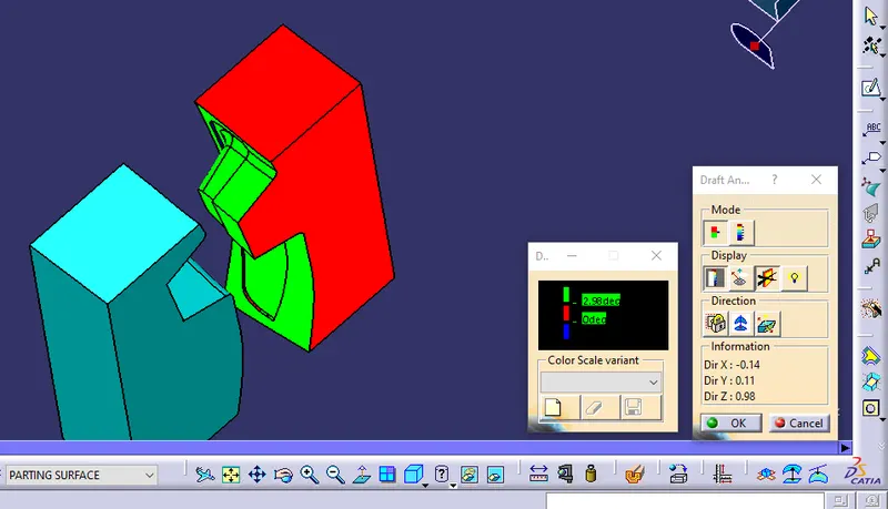
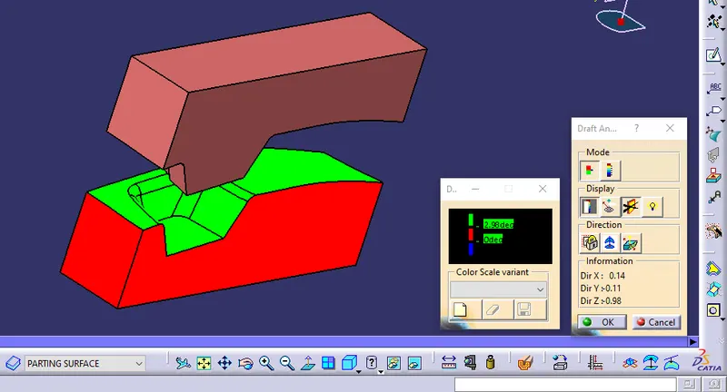
Week 8 - Challenge 6 - Core & Cavity Design
CORE AND CAVITY DESIGN AND DRAFT ANALYSIS
- Objective: To create the design of the core and cavity for plastic components and also do a draft analysis of such components.
- Tooling axis:
- Firstly, we have to create a tooling axis which is essential for designing the component and also for draft analysis.
- To create the tooling axis, I'm choosing bisecting method.
- With the help of bisecting method, I had to create a tooling axis that probably clears all the surface of class A.
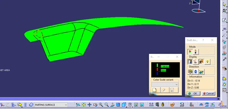
- Now, let's check the draft analysis of class A and the component Switch Bezel (refer to the below-given pic).
- Class A draft analysis:
- Switch bezel draft analysis:
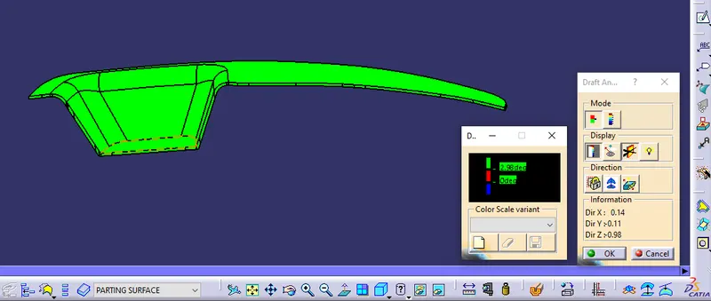
- As per the result of the draft analysis the class A and switch bezel component clearing with draft analysis.
- So, now we are all set to move forward and create the core and cavity for the Switch bezel:
- CORE AND CAVITY:
- The core is one part of the Mould which contains the upper portion of the component while the cavity is another part of the Mould which contains the lower part of the component.
- In other words, the Core is the projection of the body while the cavity is the depression of the body.
- If we combine these two cores and cavities then Mould is created.
2. PARTING SURFACE:
- During the injection mold, it contains two major components, one is the core and another is the cavity.
- At the time of the injection molding process, these two halves are pressed tightly from a sealed hollow to avoid melt flow leakage and maintain certain holding pressure.
- The pressed surface is called the parting surface.
- Usually parting surface is the biggest projection outline of the part.
- In other words, the parting surface generally separates the core and cavity.
3. PARTING LINE:
- The parting line is the junction between the core and the cavity.
- To create these cores and cavities in Catia V5, I followed the following steps:
- Extrapolate the class a surface
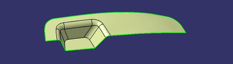
- Trim those extrapolated surfaces to the c surface.
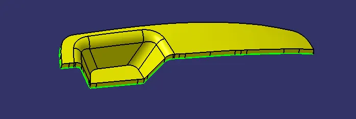
- Then trim again with b surface to get a parting surface with the component area.
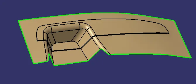
- Split the parting surface with class a to get the actual parting surface.
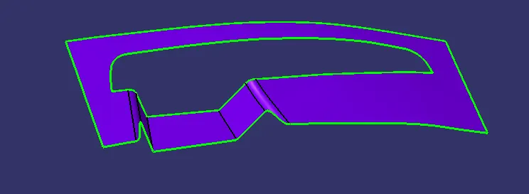
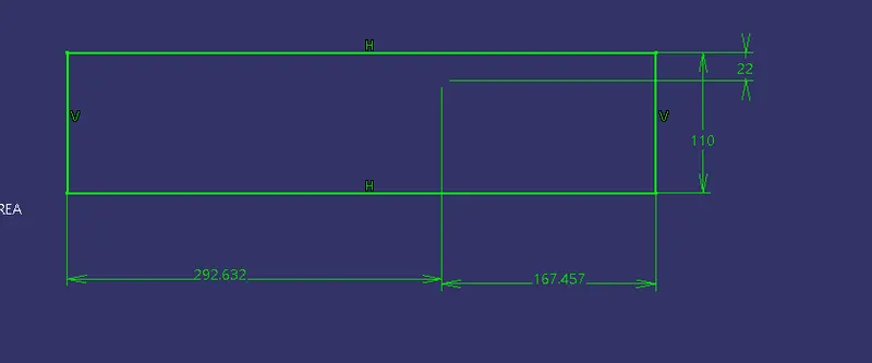
- Creating a sketch using the positioned sketch:
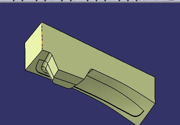
- Extrude those sketches and finally, the core is formed by performing trim and filling the top portion:
- Just performing trim with b surface and that extrude surface we finally achieve the cavity part just fill the down portion:
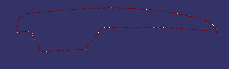
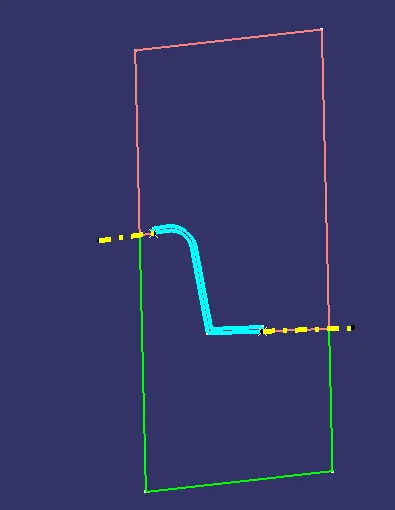
- Creating an intersection between class b and the switch bezel, to get a parting line.
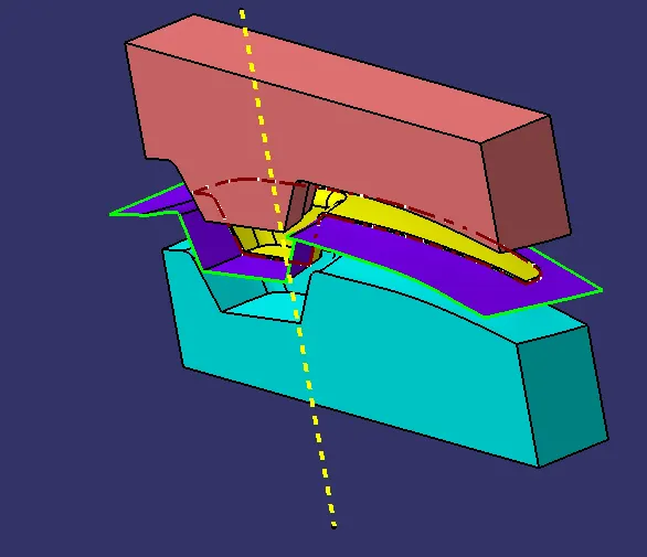
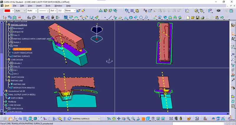
- Draft analysis of core and cavity: