Week 8 - Challenge 6 - Core & Cavity Design
CORE AND CAVITY DESIGN FOR SWITCH BEZEL
OBJECTIVE:
This Report objective is to create the Core and cavity design of the switch bezel component that we designed and to understand the parting surface and parting line for this design.
THEORY:
A parting surface can be defined as the surface where the core and cavity of the component meets. It is primarily designed for the removal of plastic products and cold slugs. The selection of parting surface is an important design factor in injection molding. With a proper parting surface selection, the mold structure can be simpler, making it easier to mold and release the plastic product, guaranteed product quality. If selected inappropriately, mold structure becomes complex, making it difficult to manufacture and affecting the surface finish and aesthetics of class-A surface in some cases. Therefore, the selection of the parting surface is of great importance to mold structure design.
PROCEDURE
Defining the tooling axis:
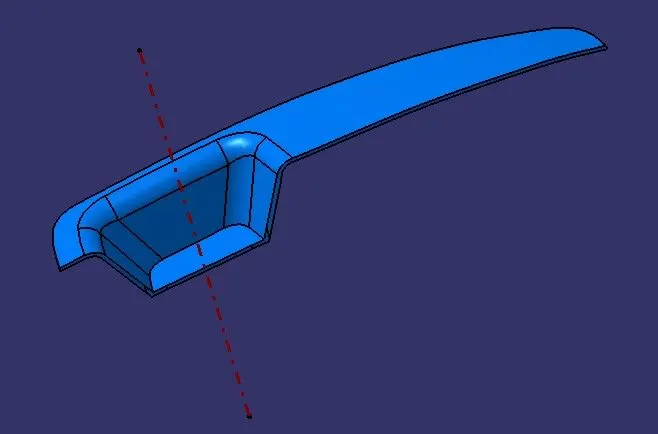
- Tooling axis is important for manufacturing any plastic component. It is the direction in which the plastic part is drawn after the completion of molding. So, it is important to have a good tooling direction.
- Generally direction normal to the flat surfaces/ holes in the component design is considered as the best tooling since it makes the whole operation easier and there by cost effective.
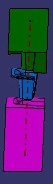
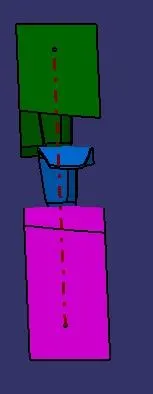
- In this case we take the initial tooling direction to be in the Z direction and then the surfaces which might create a problem with this direction are identified and the sketches for these surfaces are taken by assuming the tooling direction as the vertical axis for these sketch planes.
- The tooling direction with respect to the inclination of these surfaces is found by bisecting the lines which are derived from the inclined surfaces. Next the final tooling direction is found by bisecting the tooling directions obtained for the respective sketches.
- And the surface body is created by creating B and C surafces using class A surafce.
Draft analysis:
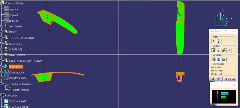
The final operation which is draft analysis is performed on the Switch Bezel which we obtained in the previous challenge with respect to the final tooling direction obtained and the results are visualized. If there are any surfaces with a draft angle less than 3 degrees it has to be corrected. In this case we are not allowed to modify the class-A surface so we need to change the tooling direction for the component so that all surfaces satisfy the minimum draft angle.
Defining the parting surface
- From the results of the draft analysis, we need to define the parting surface. In this case, we also consider the aesthetics of the class-A surface.
- If the parting surface is present on class-A, then due to the flashing defect, the class-A surface aesthetics get affected when the flash is trimmed off.
- And also from the draft analysis, we can see an extra portion present in class-B compared to class-A. So parting surface in class-B will be a good choice in this case.
Core design
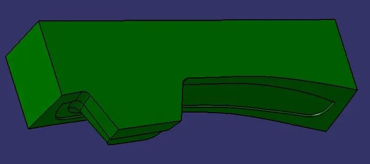
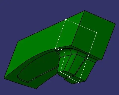
- The core is the part of the tool from where the molten plastic is injected into the space. It is the movable half of the tool.
- For the core design, we need to use the tooling direction to define the surfaces which make the core, and it is best suggested to have the parting surface in the moving half (core) because it eases the ejection process.
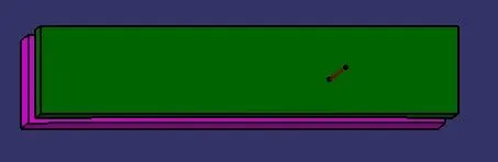
- We arrive at the surfaces that make up the core with all these considerations. By trimming them by selecting appropriate faces to give us the core's front face and extruding the simple rectangular profile, we can obtain the sidewalls of the core.
- Now, by applying the fill option to the open boundary of the sidewalls, we get a closed surface model of the core.
- This model is further converted into a solid model using the closed surface feature in the part workbench.
Cavity design
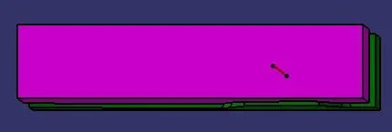
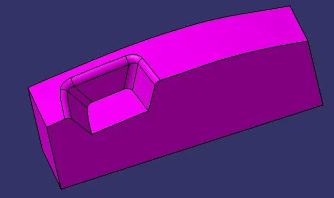
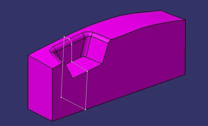
- Cavity design is similar to that of the core design. Here we take the B-surface of the final model to be the cavity's front face, trim it with the other side of the extruded surface.
- Finally, close the surfaces by applying fill to the open boundary of the side walls.
- Then the surface model is converted into a solid model using the closed surface feature in the part workbench.
Parting surface
- For the parting surface, first, we need a parting line. We can obtain this line from the intersection of class-B and class-C surfaces.
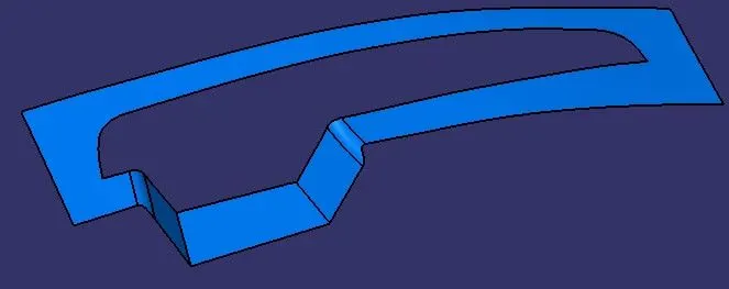
- Then the working face of the core design is trimmed with this parting line to get the parting surface. We can use the parting surface and parting line to understand the core and cavity design and in which direction the component moves after the completion injection molding process.
parting line
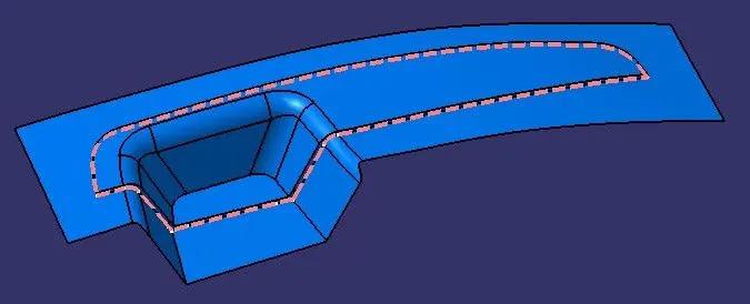
Parting surface
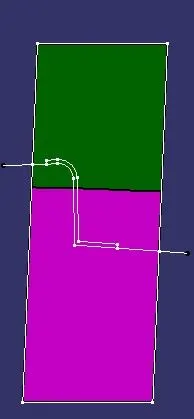
Intersection with plane after surfaces are created
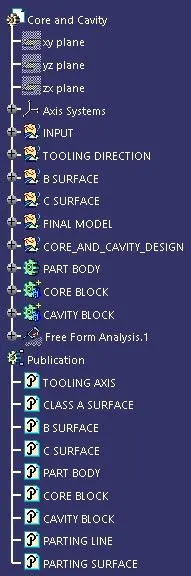
Detailed tree structure
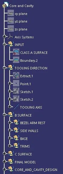
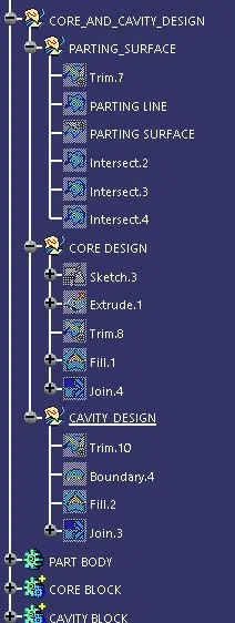
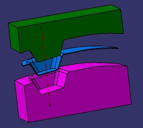
Different views of final closed body
Isometric view
Front view
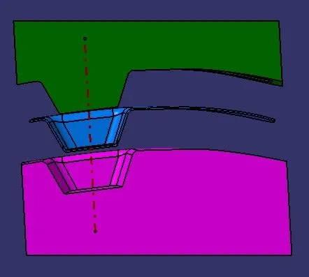
Side view
Top and bottom views