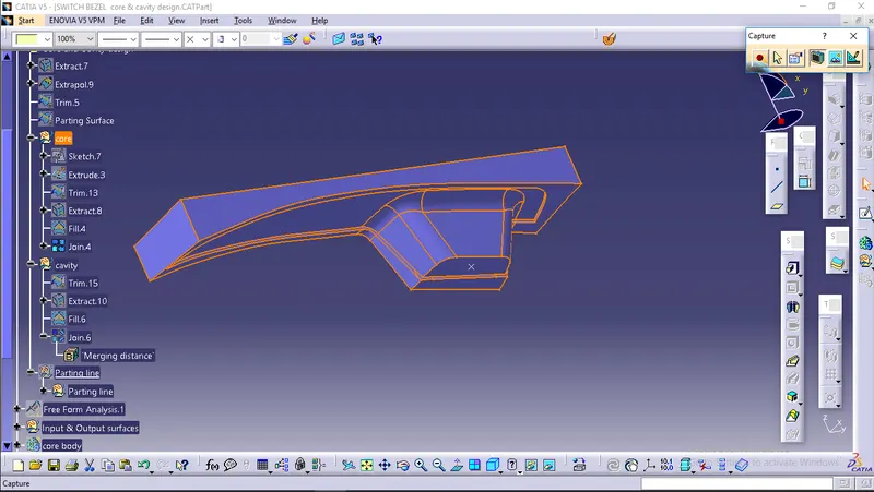
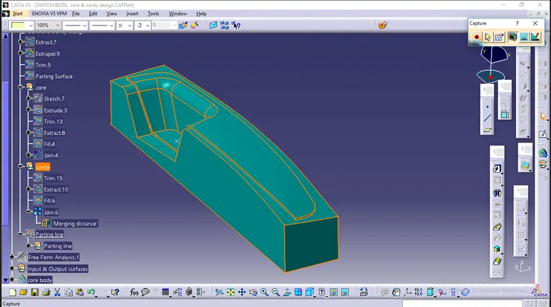
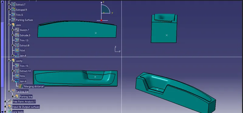
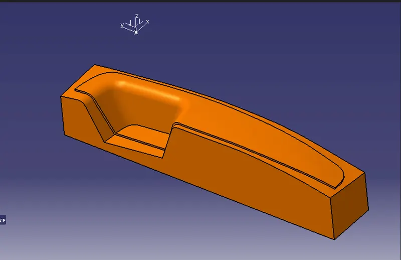
Week 8 - Challenge 6 - Core & Cavity Design
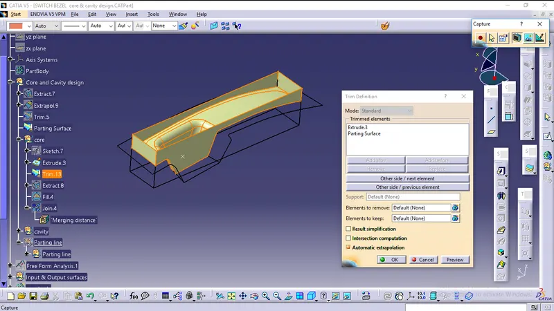
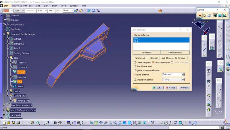
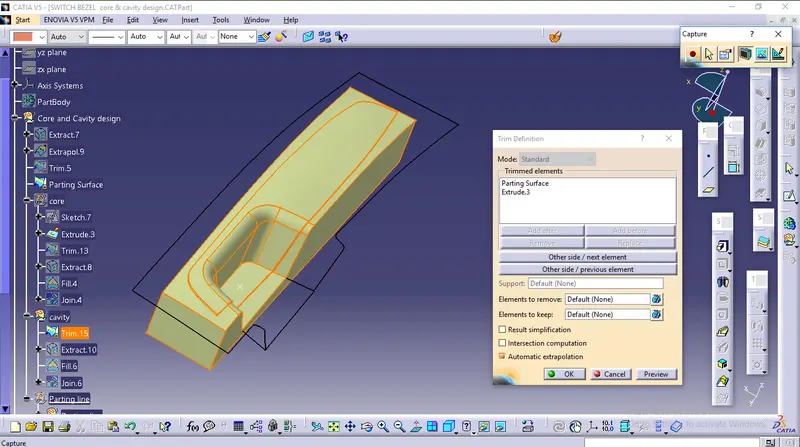
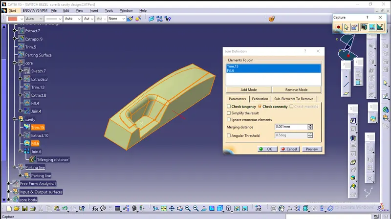
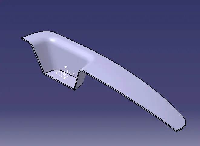
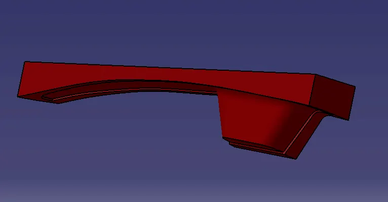
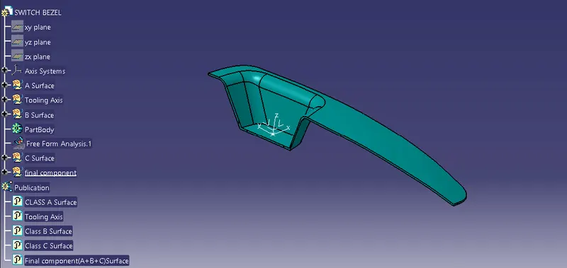
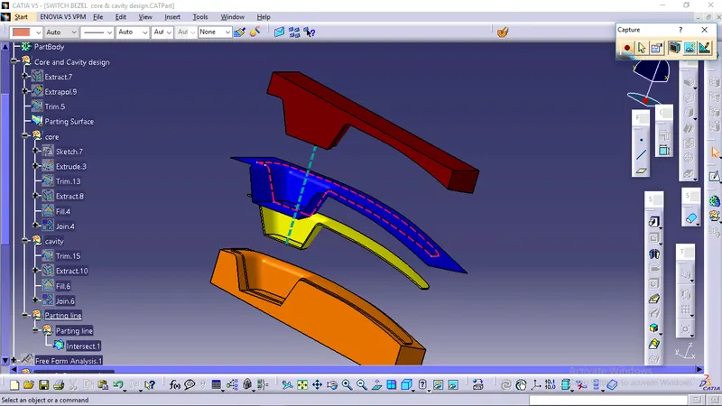
Aim: To create core and cavity block for switch Bezel considering all plastic design rules.
Steps Followed:
- Tooling Axis creation
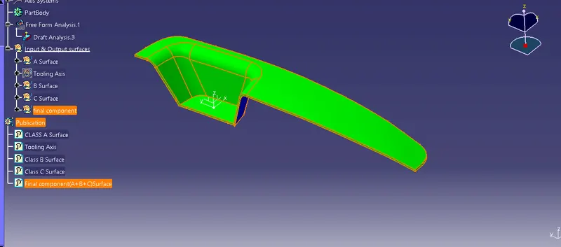
- Checking Draft analysis for created tooling Axis
- Creating parting Surface
- Creating Core Side
- Creating cavity side.
Tooling Axis:
The tooling axis is the axis in which the core cavity opens during the completion of injection molding. To create the tooling axis, we need the proper orientation or view that gives the correct features and draft available in the component.
Component view from the Z direction gives the proper view for the tool to see the features present in the geometry. To create the tooling axis from the Z direction we need the tooling axis from the X direction since it gives the draft available at the slanted part.
The tooling axis is created from the X Direction By the following Steps:
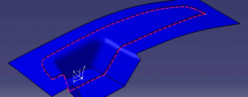
- The class A surface is Extracted
- Then the center point is created using the point, on the base surface at 0mm.
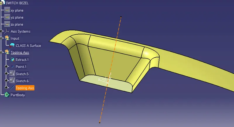
- At this point, the axis system is created.
- After switching the view of the model to the X direction and creating the tooling Axis.
Using the intersect in the ZY plane to get the boundary lines.
Then the lines are created along the slant surfaces.
Then these two lines are bisected to get the tooling axis for the X direction.
- Next switching in the Y direction and intersecting the switch Bezel part in ZX direction to get the intersecting Lines.
- Using the axis center point, a line is drawn in sketch mode and it is constrained at the angle of 6 degrees.
- At last, both the lines are bisected to get the final tooling axis.
Below line represent the tooling axis for surface.