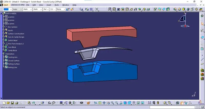
Week 8 - Challenge 6 - Core & Cavity Design
Draft Analysis of Component:
The draft analysis is done over the component with respect to the tooling axis.
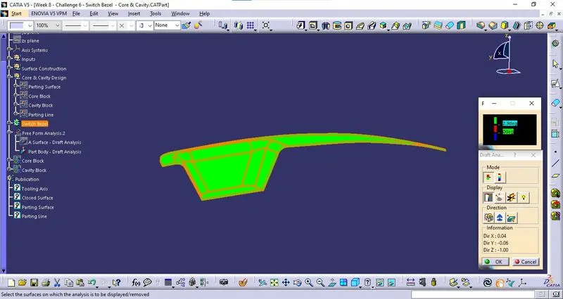
The minimum draft angel is given as 2.9 Degrees.
Parting Surface with Component:
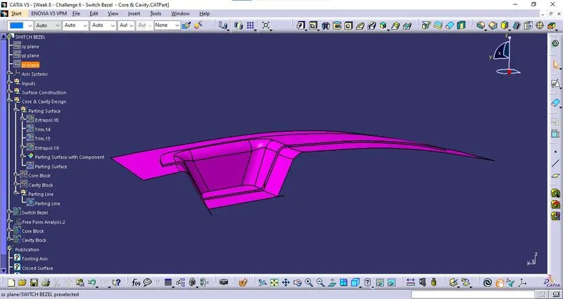
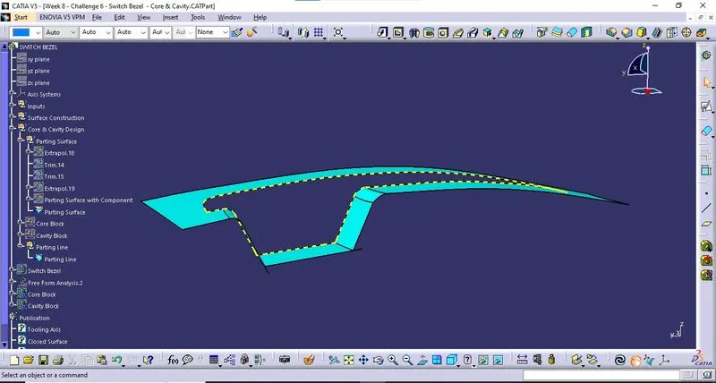
The parting Surface with Components is created by trimming the Sweep of class C Surface with B surface and then trimming that surface with B surface. Thus Parting Surface with Component is created.
Parting Line:
Intersecting the Parting Surface with the B Surface, We get a line which is the Parting Line.
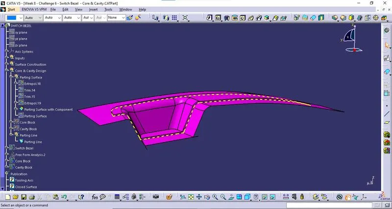
Parting Surface:
The Parting Surface is created by splitting the Parting Line with the Parting Surface with Component.
Core Block:
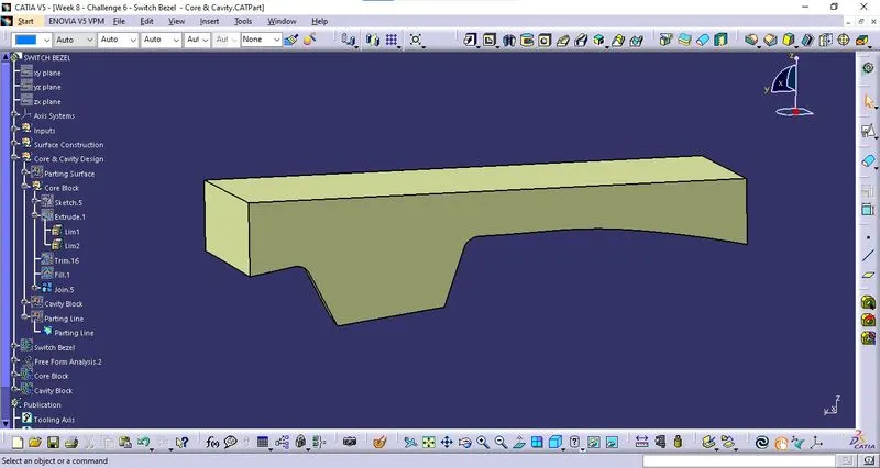
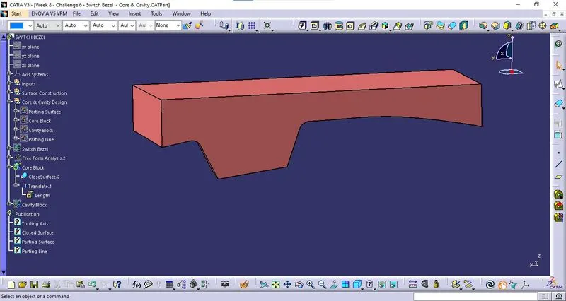
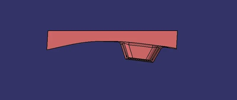
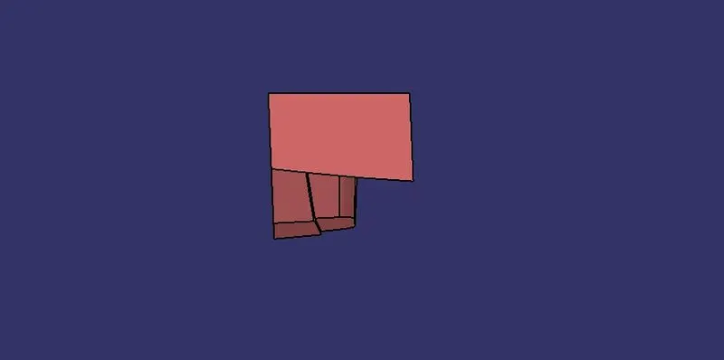
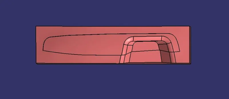
The core Block is designed by Extruding a rectangular sketch along the tooling axis and trimming it with the Parting Surface with Component along the Cavity Side. This trim is then joined with a fill to create a closed surface and this closed surface is converted into solid using Close Surface Command.
Core Block Design:
Core Block:
Isometric View:
Front View:
Side View:
Bottom View:
Cavity Block:
The core Block is designed by Extruding a rectangular sketch along the tooling axis and trimming it with the Parting Surface with Component along the Core Side. This trim is then joined with a fill to create a closed surface and this closed surface is converted into solid using Close Surface Command.
Cavity Block Design:
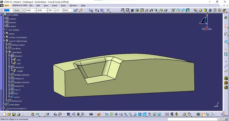
Cavity Block:
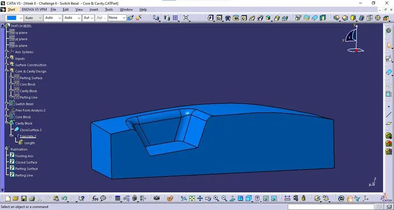
Isometric View:
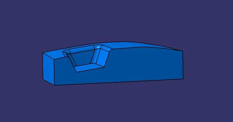
Front View:
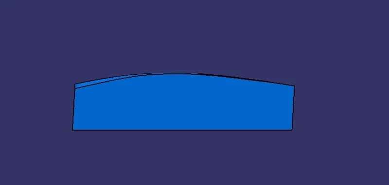
Side View:
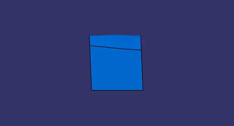
Top View:
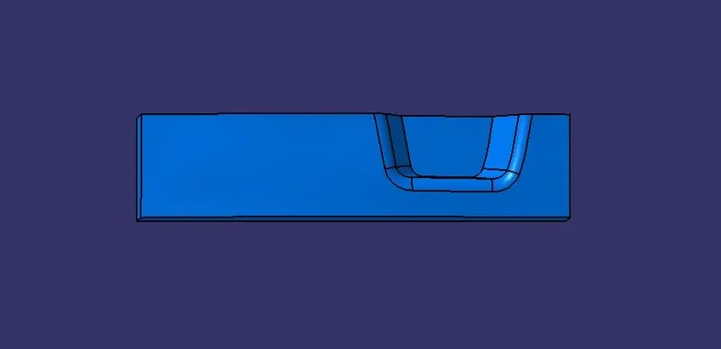
Core & Cavity Blocks with Component:
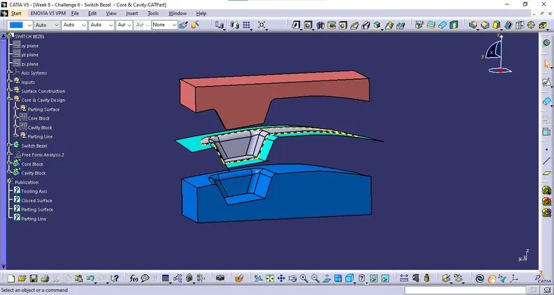
Publication:
During this process of designing the Core & Cavity Block, The Objects which are used frequently are published for ease of operation. Published Objects are,
- Tooling Axis
- Closed Surface
- Parting Surface
- Parting Line