Week 8 - Challenge 6 - Core & Cavity Design
Question:-
Create the Core and cavity blocks for the switch bezel designed in the earlier challenge
Answer:-
- Tree Structure
- Ensure Proper Tree Structure
- Geometrical sets should have a proper name based on the sketches present inside of it
- All the sketches should be created under the Geometrical set
- Use the Close Surface feature to make a solid body from the surface.
- Publications: Use the publication option and publish the below
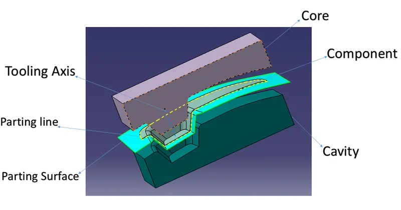
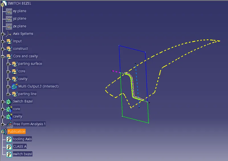
- Tooling Axis
- Switch Bezel Solid / Surface body
- Parting Line and Parting Surface
1.Tree structure:-

2.Tooling Axis:-
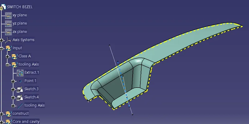
Steps:-
- create a point on the bottom surface
- make a intersecting line and find the bisect line through that YZ axis
- Find the other bisect oh other plane of XY axis
- create the bisect from those bisect lines
- it will be the tooling axis
Bisecting method:-
- For doing this you should find out the what is the best tooling direction.
- Foe doing that to rotate the part and see all directions and choose the which direction will be comfortable.
- Then create the point on the base mostly create the point where the hole or pockets are given.
- And after that insert tooling axis in that point.
- Then first see in x direction it ill clear the all faces of parts if not create a plane and intersect to each other.
- The fallowing window will be appeared.
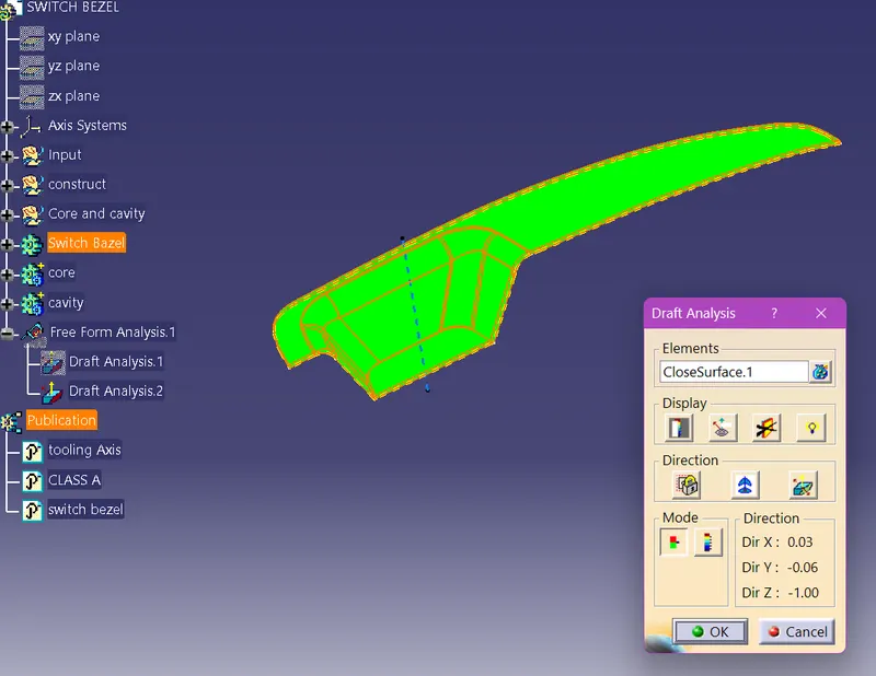
3. Draft Anlysis :-
- The draft angle is the amount of taper for molded or cast parts perpendicular to the parting line.
- It can be measured in degrees or mm/mm (in/in).
- As plastic cools, it shrinks and therefore shrinks onto molding surfaces.
- Because of this and a few other reasons, we draft (angle) the walls of the plastic part, so as the part is removed it breaks free from the molding surfaces easier and without dragging.
- A functional part for injection molding has to have drafts facing both cavity and core sides to reduce the risk of damage to the parts and ensure ejection.
- What’s also important is to overcome the vacuum forces by letting air in between the metal and the plastic for the part to release properly.
- Adding an adequate draft angle ensures that warpage upon ejection is prevented while maintaining a decent cosmetic finish.
- Draft angles are generally a requirement of injection molding design (though there are a select few soft materials, like nylon, that can get away with draft angles of zero).
- Draft should be a part of design for manufacture, and Plastic Product Designer should be aware of its need at the outset of the design process. This allows considerations for design requirements to be taken into account
-
Nominal Values for Draft angle:
- 3 Degrees is nominal Draft.
- 5 Degrees can also be manufactured. But it will increase the manufacturing cost.
- 7 Degrees for textured surface.
Importance of DRAFT in Injection Molding:
- Reduces the chance of damage to the part due to friction during release
- Reduces wear and tear and chances of damage to the mold
- Ensures a uniform, smooth, unscratched finish when required
- Ensures the integrity and uniformity of other surface finishes and textures
- Reduces overall cooling time by lessening or eliminating the need for unconventional ejection setups
- Most, if not all, of these benefits offer either direct or indirect overall production cost reductions.
Steps followed for Draft Analysis:
- The part created has to be changed to Material mode in display frame.
- Compass is enabled. Align compass along with tooling direction.
- Lock command is then applied to fix compass along with tooling axis
- Color codes are classified and Draft angle is applied.
- Running point analysis is used to display permissible draft angle
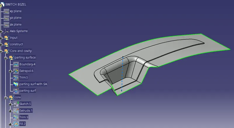
4. PARTING SURFACE:-
- Generally injection mold has two major components : the movable half and the fixed half, during the injecction molding process, these two halves are pressed tightly from a sealed hollow to avoid the melt flow leakage and maintain certain holding pressure, the pressed surface are called parting surface , usually parting surface are the biggest projection outline of the part.
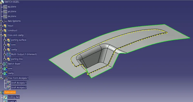
5. PARTING LINE
- A parting line is an inevitable part of injection molded products.
- It is the line of separation between where two halves of a mold meet.
- It manifests itself on injection molded parts as a line that runs the entire perimeter of the part.
- In most parts, it is just a line that runs straight down the middle.
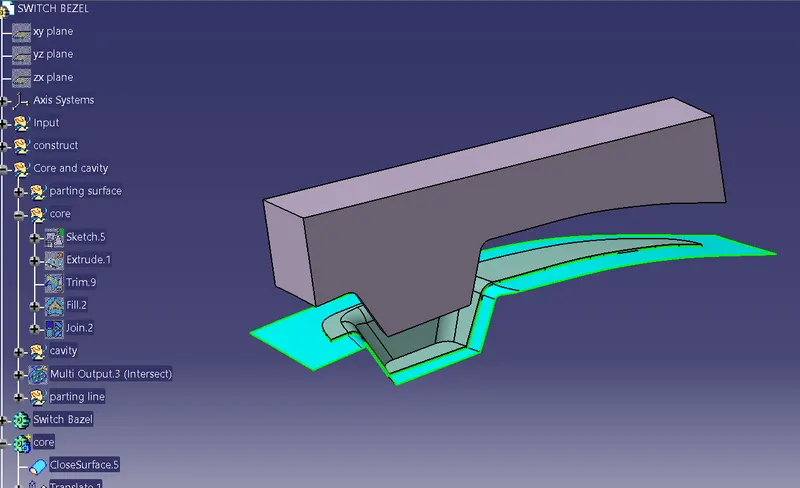
6. CORE DESIGN
- Core - A portion of the mold that goes inside a cavity to form the interior of a hollow part.
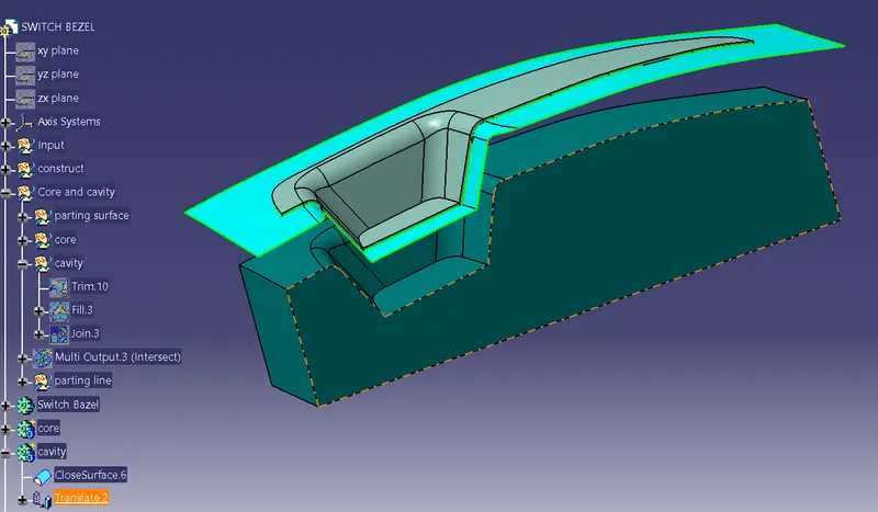
- Core-cavity - A term used to describe a mold created by mating A-side and B-side mold halves.
7. CAVITY DESIGN:-
8. Detailing:-
9.Intersections:-
10. views:-
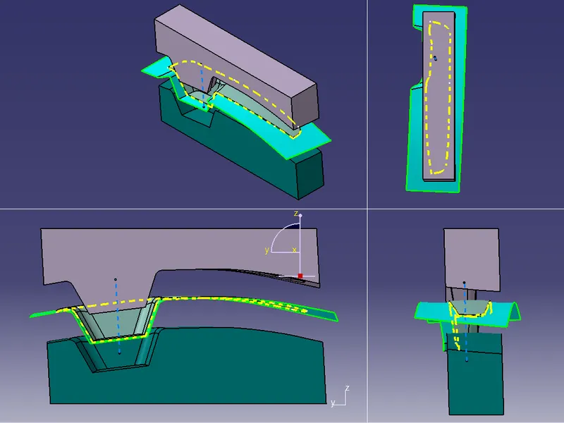
Results:-
- Submission in challenge box
- Above images/screenshots inserted into the challenge box
- Screenshots of the Draft analysis report for both the switch bezel plastic component
- Screenshots of the core and cavity blocks in various orientations (Isometric, Front, Side, and Top View)