Week 8 - Challenge 6 - Core & Cavity Design
Core and Cavity Block creation
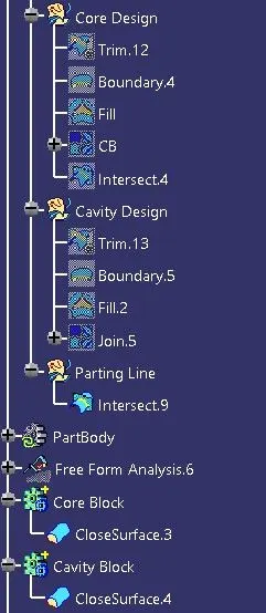
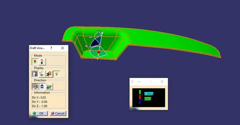
Step 1: Draft analysis:
Prior to creation of core and cavity block, a detailed draft analysis should be done. The core side of the component should have a positive draft of atleast 3degrees. It is posible to create components with tight draft angles upto 0.5 degrees, but would be costly process. Generally, draft upto 3 degrees can be easily achived.
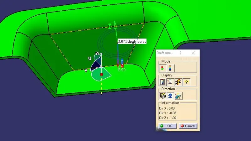
Step 2: Parting surface creation:
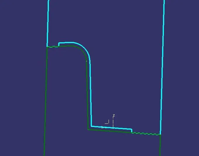
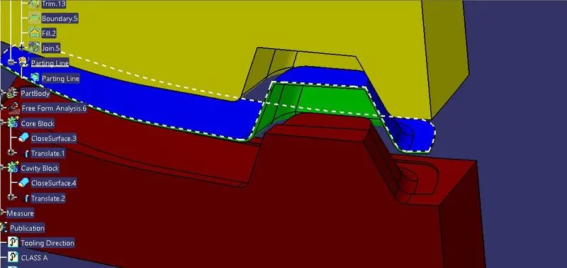
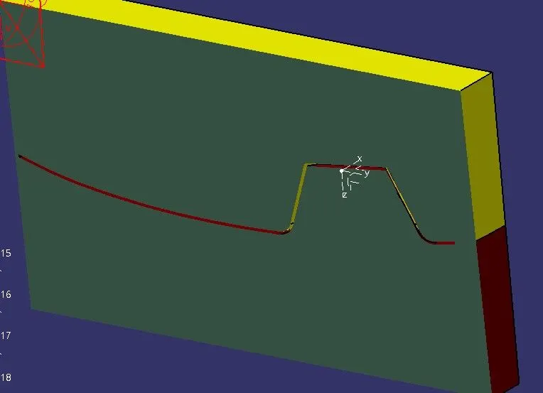
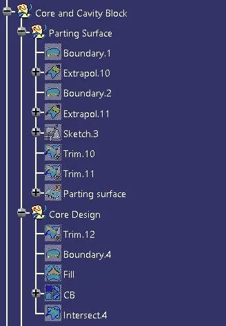
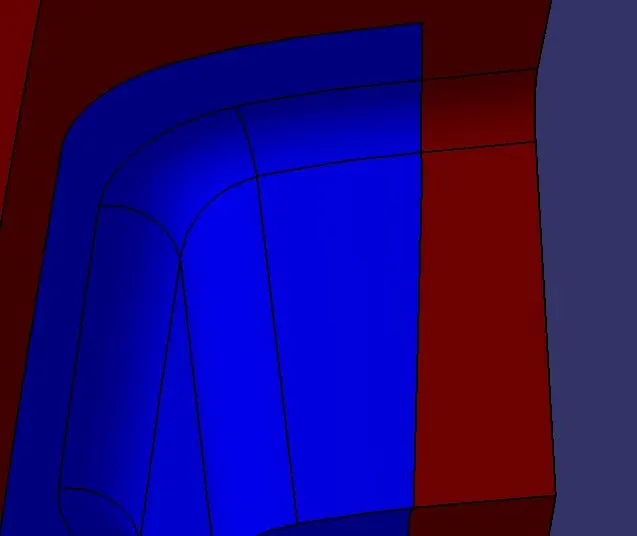
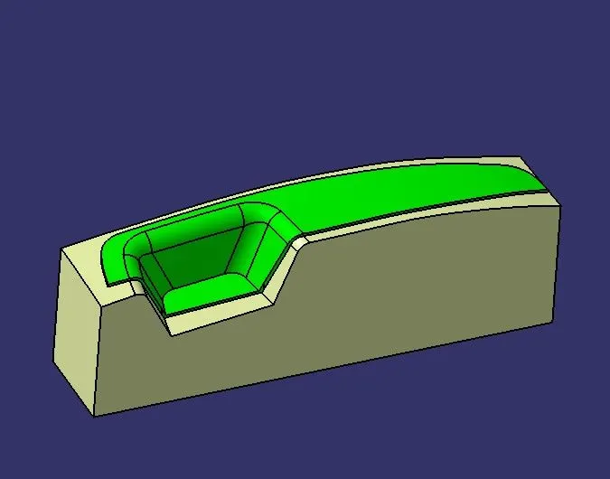
Parting surfaces are created at the extermities of Class A, B and C surfaces. It has to be noted that the parting line should never be on Class A surface as it could create flash defect. Parting surfaces are created by triming B surface with joined A and C surfaces. Parting line would be created at boundary of joint between B and C surface. Later, outer boundaries are extruded along the tooling direction and the excess portions are cut to form core and cavity block.
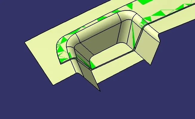
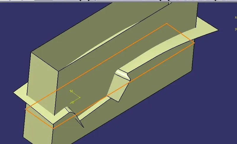
Step 3: Core and Cavity block creation
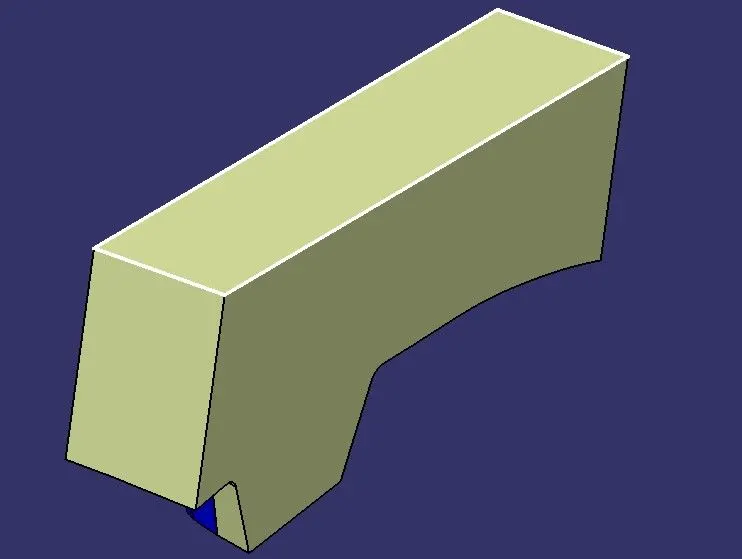
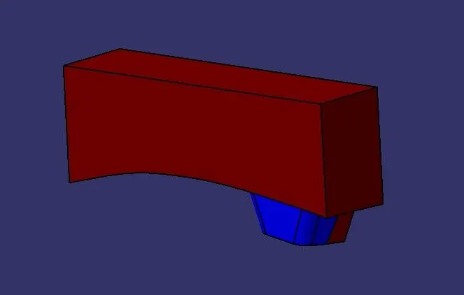
Core block and cavity block has to be created by trimming the parting surfaces with the outer boundary with the parting surfaces. The open boundary formed on top are later closed using fill command and later joined with it and made to a solid block by using close surface command.
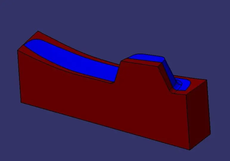
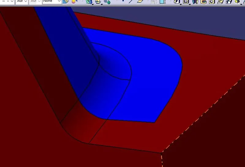
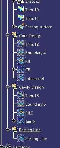
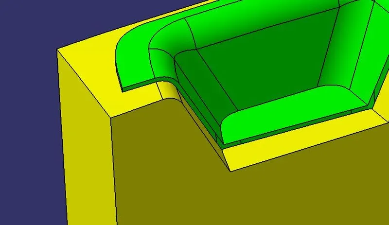
Step 4: Parting line creation
Parting line is created by taking intersection between Class B surface and Class C surface.
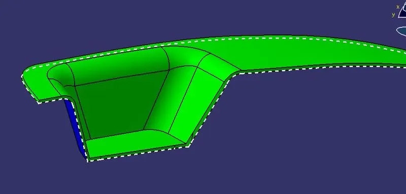
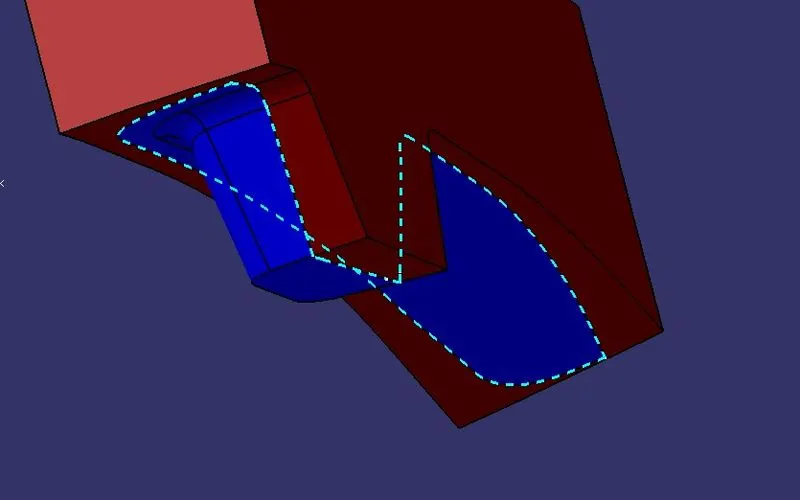
Step 5: Final inspection
After completion of all the above steps, a final inspection is done to ensure that core and cavity is properly created. This can be done by instpecting intersection between core and cavity blocks. This is to ensure that there are no gaps and parting line is properly formed. It can also be checked by looking in section views.