Week 8 - Challenge 6 - Core & Cavity Design
Parting Surface:
- In injection Moulding Process, Mold has 2 parts, Fixed Half and Movable half, During Injection the two halves are tightly presses and form a sealed hollow to avoid any leakage of liquid plastic.
- The pressed surfaces are called Parting surface. Certain holding pressure has to be maintained.
- Design principles for parting surface:
- Parting surfaces should be made as simple as possible.
- Flat faces are easy and match and manufacture rather than curved surfaces.
- Ensure appearance requirement of the molded part. On the parting surface usually a Flash or mismatch occurs, Additionally, minimum amount of liquid plastic get pressed against the parting halves which makes the parting line evident of plastic parts once released from mould. Hence, parting surface never be designed on anyy high quality requirement surfaces such as Class A surface. Always design parting surface at boundary of Class B surface.
- Dimensional Accurancy of Manufactured parts.
- If possibel parting surface should be placed at the end of the mold flow. This will be advantageous for filling and Venting.
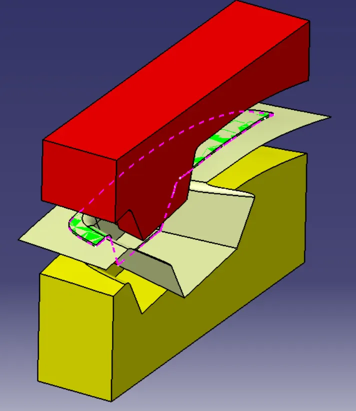
Parting Line: The intersection between the parting surface and the component is called the Parting Line.
It is the exact junction where the Core and Cavity Closes.
In our case the boundary of the B surface.
Procedure:
- Strart the process studying the draft analysis and Tooling Axis to decide the surface that will be cleared by core and cavity repectively.
- The green face are cleared by 1 half of the mold and Red faces are cleared by the other half of the mold.
- The core is the male part which forms the internal shape of molding. It makes the concave shape. Usually the fixed side. In design of swtich bezel we use the cleared Green Surface (Class A surface and Class C) side for Core.
- The cavity is the female part which forms external shape of molding. It makes a concave shape. Usually the moving side. In design for switch bezel we use the opposite red surface (Class B surface) side for Cavity.
- We observe that Class A and Class C surface are cleared by our tooling Axis.
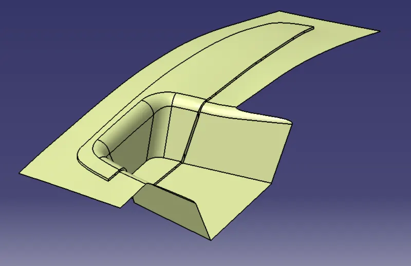
Also, we must always keep the parting line on the surface which will not be evident to the end user. - Extract the class A surface and Class C surface and trim to get the following shape.
This is going to be the surface of core.
We observe that it clears all the Class A and Class C faces that were clearing the tooling Axis.
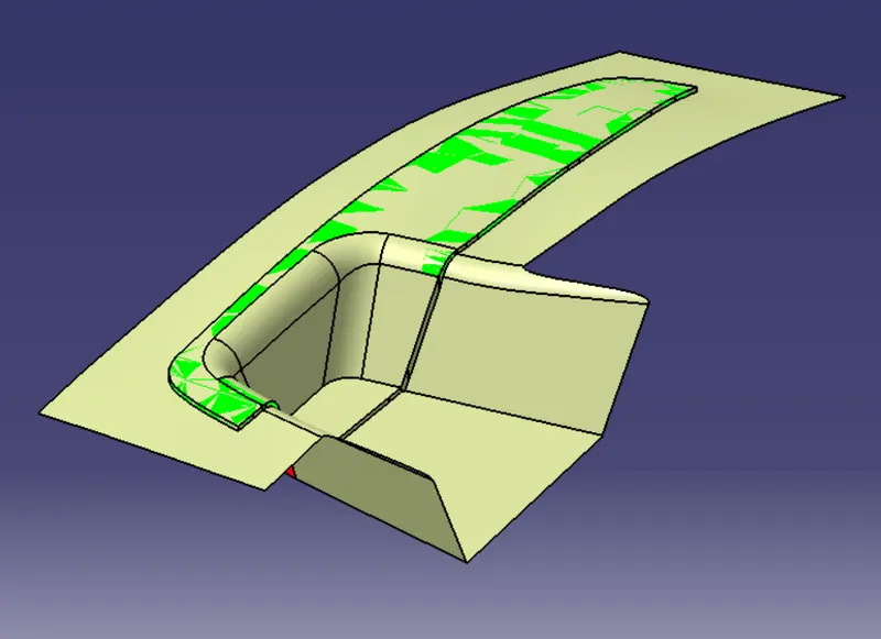
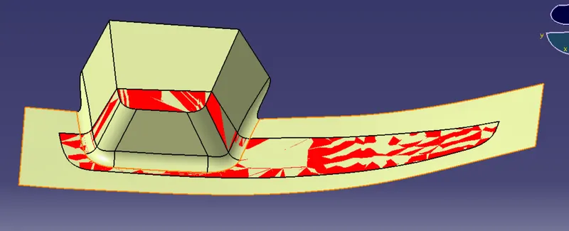
- Similarly, extract Class B surface.
This is going to be the surface of Cavity.
We observe that the extracted class B is sufficiently clearing the red faces of our component.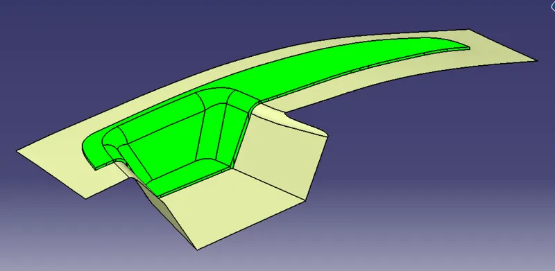
- Extrude a rectangular surface around the final core and cavity surface and split to get the complete Core and Cavity Block.
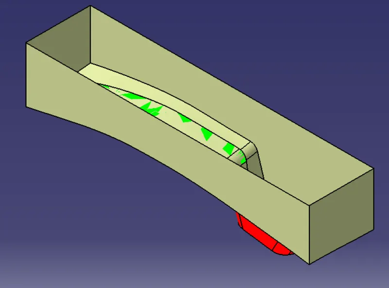
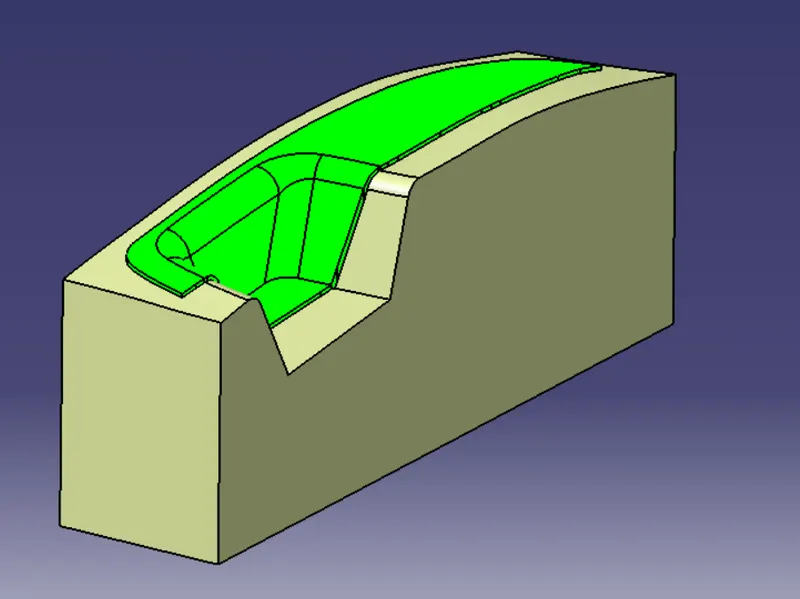
- Fill the surface to get a solid.Final product will look like following:
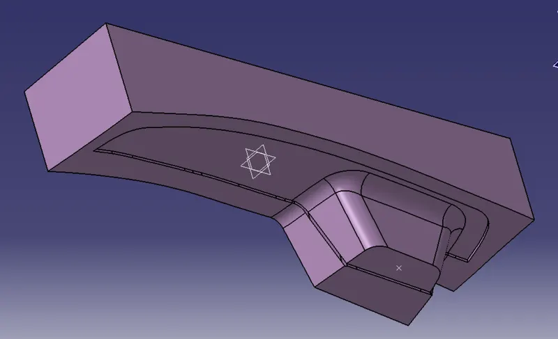
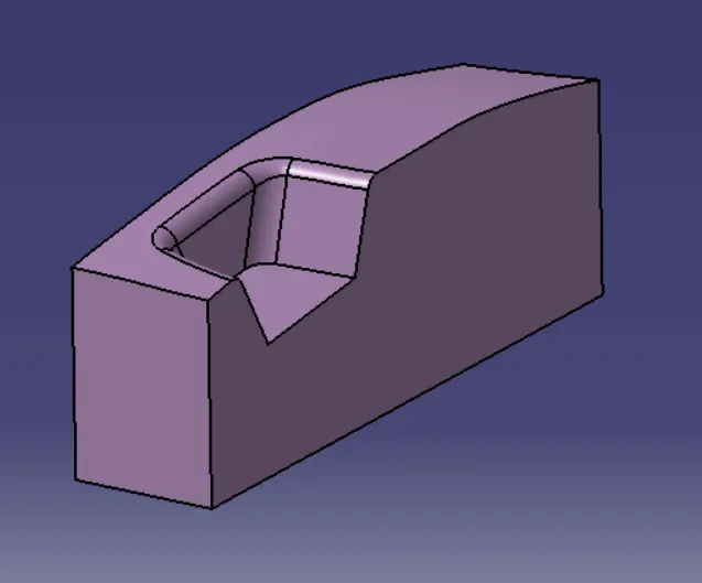
- Visualizing the Mould sturcture: