Week 8 - Challenge 6 - Core & Cavity Design
AIM: To Create the Core and cavity blocks for the switch bezel component.
Objective
- While Preparing the core and Cavity is mainly dends on Plastic componet and Tooling Direction.
- Basicaly set up Core and Cavity depends up on the Part size.
- Also moment (or) Direction follows the Tooling Direction.
1) Tooling Direction : Tooling direction is main consideration for plastic part and mold parts because it defines movement of mold part and possibility of plastic part to come-out from mold part (Core and Cavity).
- In Molding machine arrangement is given to open the mold along a direction which is known as Tooling Direction.
- In other words. The mold is built from two separate halves (Core and Cavity) and tooling direction basically define the direction of mold pulls apart.
- Tooling direction is known as primary direction.
Preparation of Tooling Direction.
While creating the tooling direction in given class A surface. Chose suitable Side walls and draw the line direction of axis. as shown the below fig 1.1.
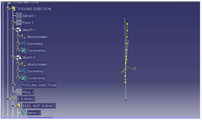
Fig 1.1.
2) PUBLICATION :
- It helps the component to make it visible and navigate easily.
- To publish the component go to tools > publications and then select the tooling axis and the class A surface.
- A separate tree structure is formed under the main part.
Below fig 2.1 shown the Publication.
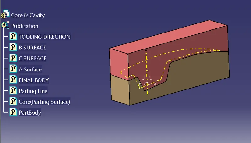
Fig2.1.
3) DRAFT ANALYSIS
The draft angle of plastic part prevents the plastic parts from sticking to the mold, which causes the plastic part to deform. The draft angle is generally 3°-5°.
- While performing the draft analysis in catia Chose the Feature Draft Analysis.
- Choose the compass and then move the compass on Tooling Direction.
- Choose Part then it will indicates the in colour code for all dimensions.
Below Fig 1.3 shown the draft analysis
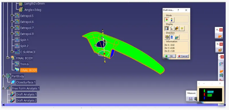
Fig 1.3.
4) PARTING SURFACE
The right parting surface guarantees that the design of the core and cavity is suitable. It also ensures that the plastic part can be taken out of the mold. In Inventor Mold Design, the parting surface is divided into two parts, the patching surface and the runoff surface.
Below Fig 4.1 Shown Parting Surface.
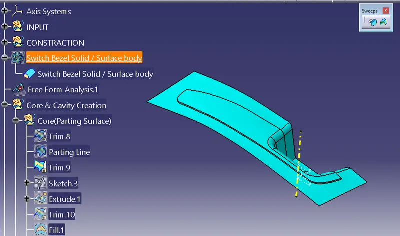
Fig 4.1.
5) PARTING LINE
The parting line of a die cast component represents where the two different sides of the mold come together. This line often (but not always) marks the border between the inside and outside of the part. The location of the parting line indicates which side of the die is the cover and which is considered the ejector.
Below Fig 5.1 Shown Parting Line.
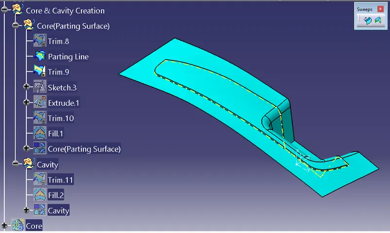
Fig 5.1.
6) CORE DESIGN
Core is the side of the tool where the plastic part is injected from; The upper half of the mold is called CORE.
Below Fig 6.1 Shown CORE DESIGN.
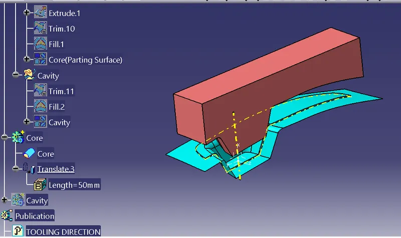
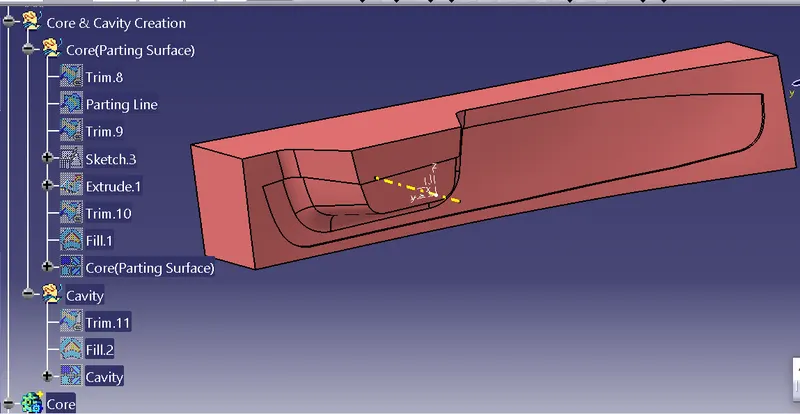
Fig 6.1.
7) CAVITY DESIGN
A mold is a hollow form typically made from stainless steel that has plastic injected into it to manufacture a plastic part. The plastic is inserted into the mold cavity, which is a hole in the mold shaped like the desired part.
Below Fig 7.1 Shown CAVITY DESIGN.
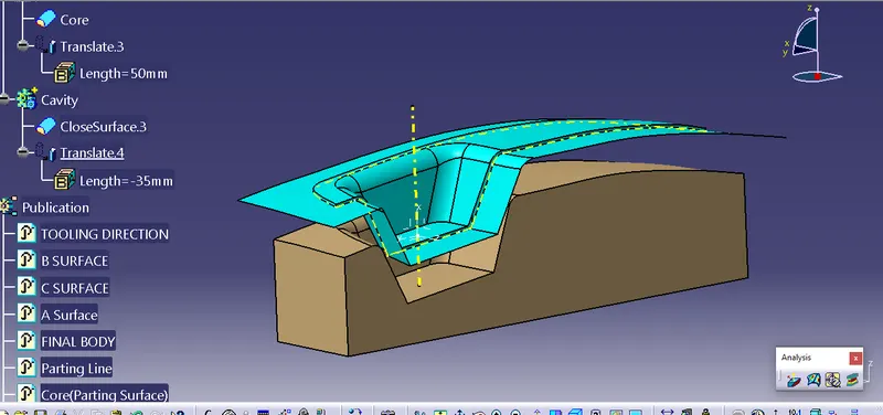
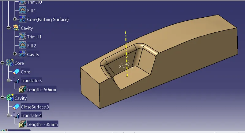
Fig 7.1.
8) 3D Views of Core.
Below fig (8.1 to 8.4) shown solid model of core(Isometric, Front, Side, and Top View).
Isometric View.
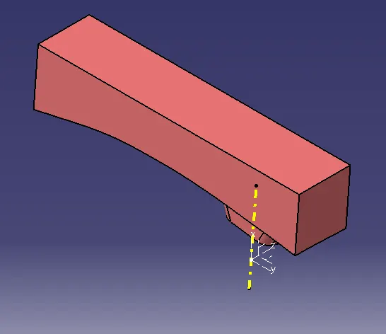
Fig 8.1.
Front View.
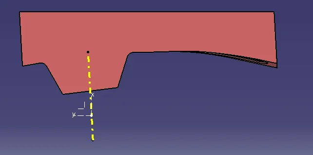
Fig 8.2.
Side View.
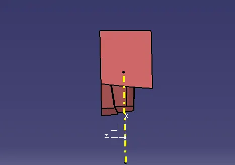
Fig 8.3.
Top View.
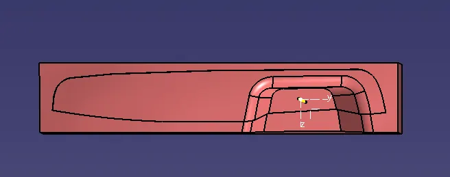
Fig 8.4.
9) 3D Views of Cavity.
Below fig (9.1 to 9.4) shown solid model of Cavity(Isometric, Front, Side, and Top View).
Isometric View
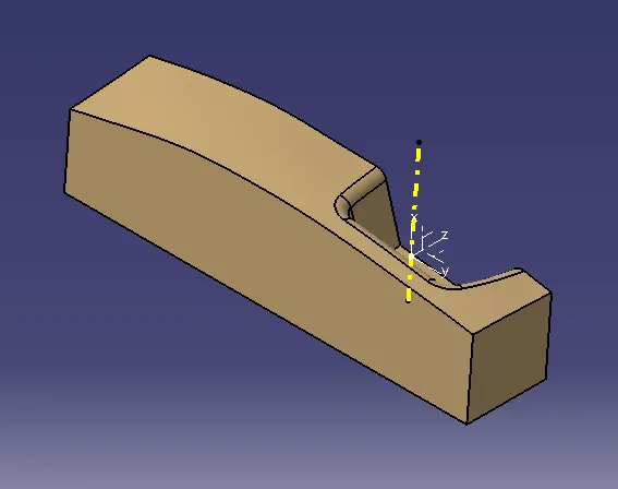
Fig 9.1.
Front View.
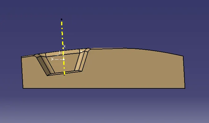
Fig 9.2.
Side View.
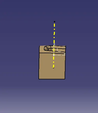
Fig 9.3.
Top View.
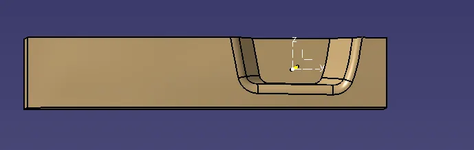
Fig 9.4.
CONCLUSION : The Core and cavity blocks for the switch bezel component is created by considering Design Methodology.