Fender Design Challenge
AIM: By using the skin data develope the fender as per master section.
Objective : 1.Intruduction to Fender.
2.Fender types.
3.Fender design.
4.Final design.
5.Conclusion.
1.Intruductin to Fender : Is the American english term for the part of an automobile,motorcycle or other vehicle body. That frames the a wheel well. Its primary purpose is to prevent the sand, mud, rocks, liquides, and other road spray from being thrown in to the air by rotating tyre. Basicaly it was an made up of steel are plastic.
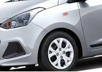
fig 1.1 Fender.
2.Types Of fender.
2.1 Full type : The fender openings for the whell wells tend to be much larger than the diameter of the tire because they do not move with the tire suspension and consequently muat be large to allow the full range of tire motion on the suspension without touching the interior of the wheel well.
2.2 Half type : In this type material required less as compared to full hance weight and wastage of material is less. Then it will be reduces the cost and increses the efficency of vehicle.
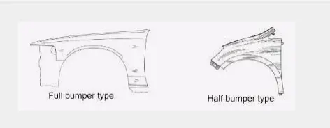
Fig 2.1 Full & half type fender.
3 Fender Design.
3.1 Drip Area.
3.2 Bumper Mounting Region.
3.3 Sill Mounting Region.
3.4 A-Pillar Mounting Region.
3.5 Wheel Arc Mounting Region.
3.1 Drip Area.
Below figure 3.1(a) is used to as a master section to create drip area.
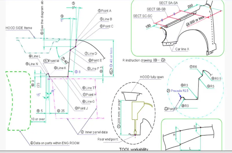
Fig 3.1(a) Master Section.
Drip ara is the critical mounting area located in side the engine compartment. Designed according to the master section provided and optimal opening angle is mainted to make it look well while seeing from out side.
While designing the drip area from front side of the fender to keep 150mm distance and back end of the fender have to keep the 200mm distance.
Vertical distance of the drip mounting is maintained less than 60mm to avoid the spring back effect.
Drip area is mounted to engine compartment by weld nuts. Drip area shown in below fig 3.1(b).
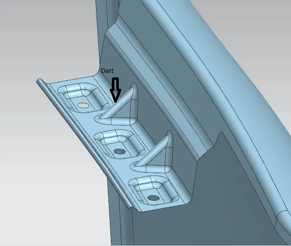
Fig 3.1(b). Drip Area.
Dart is a narrow ridge of matal used to strengthen a flange of a part. The dart is formed into the edge of the flange and the part.
3.2 Bumper Mounting Region.
This one is the mountaing of the fender to bumper region. Mostly bumpers are made up of plastic which can covers the bottom front and back part of the car.
It protect the car at time of collisions. In the below fig 3.2(a) shown bumper mounting region.
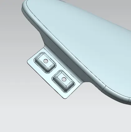
Fig 3.2(a) Bumper Mounting Region.
3.3 Sill Mounting Region.
The mounting area at the panel directly to the bottom of the door supproting floor. Which is bolted together and sill inner cover could covers the fasteners. The sill mounting region shown below fig 3.3(a).
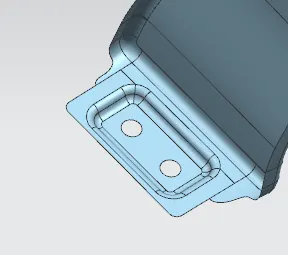
Fig 3.3(a) Sill mounting Region.
3.4 A Pillar Mounting Region.
A pillar mounting is on the car either side of the front windshield, which is the region the windshield in the place. It mounted on the A Pillar by means of the bolts and this are covered by out side view mirrors. Below fig 3.4(a) shown A Pillar mounting region.
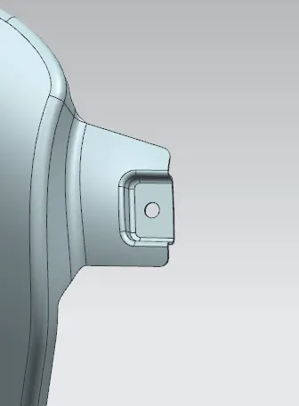
Fig 3.4(a) A Pillar Mounting Region.
3.5 Wheel Arc Mounting Region.
This wheel arc area help to mounting the baffle plates with help of pins. This region shown below fig 3.5(a).
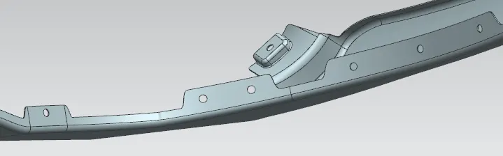
Fig 3.5(a) Wheel arc mounting.
4. Final Design.
As below shown fig 4.1(a) final design of finder. while designing considering all engineering parameters.
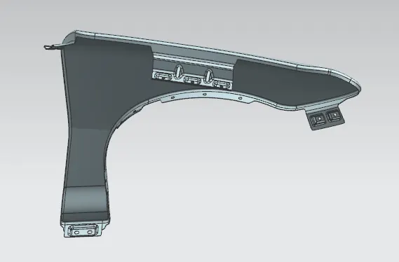
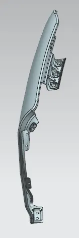
Fig 4.1(a) Final design.
Final design having an 0.75mm thickness.
5.Conclusion.
Fender design is completed by using the NX CAD software with satisfying all design constrains and strengthening the design as requried.