Week 8 - Challenge 6 - Core & Cavity Design
AIM:
To Create the Core and cavity blocks for the switch bezel with the help designed switch bezel. At the end perform a parting line transition for the core and cavity operation for the model.
PROJECT DETAIL
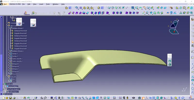
Here the part body of the switch bezel was provided as in OEMs. we need to create Core & Cavity and Parting lines & intersections lines for the mold & cavity. Then I created a solid body for the core and cavity. Finally, successfully performed the translation to the core and cavity. The steps to be followed for the creation of this component are given below
PARTING LINE
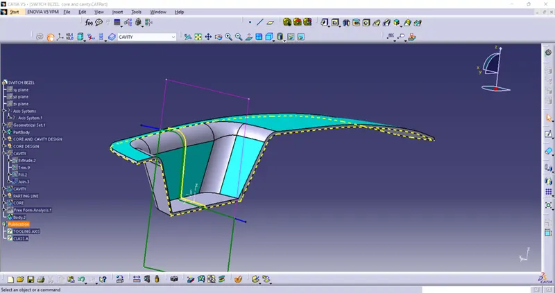
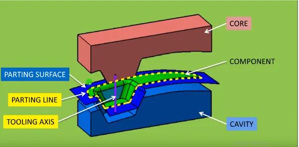
The parting line indicates the direction of the line of the draw for the mold or the point where you can separate the two halves of the mold to release the part without damage. Usually, the parting line is down the middle of the part, but this varies due to part geometry. The parting line determines the direction to draft features for easy removal from the mold.
PARTING SURFACE
A parting surface is a surface that separates the mold block into two parts – the core and the cavity.
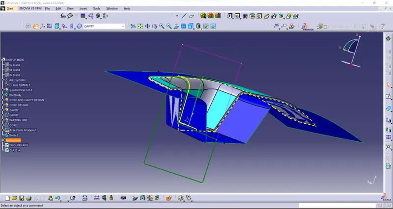
The portion of the mold block above the Dark blue surface will form the cavity, and the part below it will create the core.
PROCEDURE:
- Parting Surface
- Tooling axis
- Creating core
- Creating cavity
- Solid body for core &cavity
- Conclusion
Tooling Aixs:
It is the direction in which the mold or core & cavity open. Part drafts are given along this axis.
Tooling operation:
To decide on the tooling axis, the component should be completely clearing the Tooling axis in the given specific direction.
The first one visually checks. We can check, which one is possible for Tooling Direction. We can check all x, y & z directions. If you have a hole, what will happen, you have a separate side core for a specific hole. In this draft analysis of switch bezel Z – direction the possible Tooling direction and tooling axis are created by bisecting method.
- Creating Core:
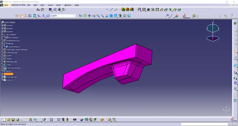
Cavity and core are used in the injection molding process, where the concave part of the mold is the cavity and the convex part is the core. The cavity and core are used in pairs, with the cavity also referred to as the female mold and the core as the male mold.
- Creating cavity
Cavity and core are used in the injection molding process, where the concave part of the mold is the cavity and the convex part is the core. The cavity and core are used in pairs, with the cavity also referred to as the female mold and the core as the male mold.
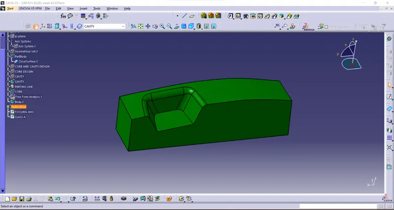
- Solid body for core &cavity
The extruded rectangle & fill at the top& bottom of the rectangle is joined together and form a solid surface or a Part body.
And translate the both core and cavity for distance and see the direction of the molding.
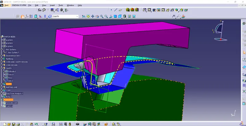
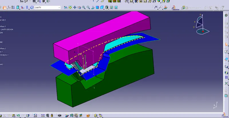
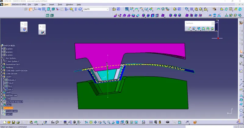
CONCLUSION: Obtained core and cavity of the switch bezel from the given following procedure