Week 8 - Challenge 6 - Core & Cavity Design
AIM:
- To create core and cavity for bezel switch considering all the design rules.
TOOLING AXIS:
- Tooling axis is the defined axis to perform the manufacturing process within the injection molding according to its direction.
CREATION OF TOOLING AXIS:
To create the tooling axis for the switch bezel design.
It has three adjacent tapered faces with the bottom closing base surface.
So we can't create the tooling axis for entire tapered faces.
First, we analyze the model in which direction is suitable for the appropriate particular tapered faces.
Create the tooling axis perpendicular to the bottom face and parallel to both sides of tapered faces and create the tooling axis perpendicular to the same bottom face and parallel to the remaining side tapered face then bisecting the two reference tooling axis to get the main tooling axis.
REFERENCE TOOLING AXIS 1:
- Extract the bottom face from the class A surface.
- Make a point at the center of the bottom face and position the axis system on the point.
- Create a positioned sketch with reference to the yz plane.
- Cut the part by sketch plane.
- Intersect the plane with class A surface by using the intersecting 3D element command.
- Sketch the line on the intersecting profile which is lying parallel to the considerable tooling axis.
- Create the bisecting line to reference of sketched line on the intersection profile and called it as reference tooling axis 1.
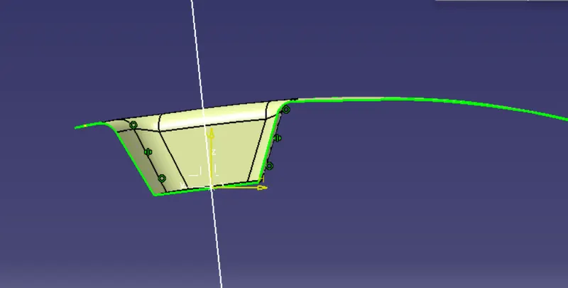
REFERENCE TOOLING AXIS 2:
- Create a positioned sketch with reference to the zx plane.
- Cut the part by sketch plane.
- Intersect the plane with class A surface by using the intersecting 3D element command.
- Here one side of intersecting profile takes place. so sketch the line on intersecting profile which is lying parallel to the considerable tooling axis.
- Sketch an inclined line from point to sketched line on the intersecting profile and give the angle of 5 degrees between the two lines to maintain the nominal draft while performing the draft analysis.
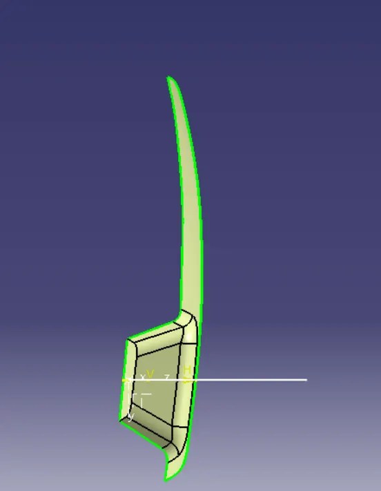
MAIN TOOLING AXIS:
- Finally create the bisecting line by reference to tooling axis 1 and 2.
- Bisected line is called as main tooling axis.
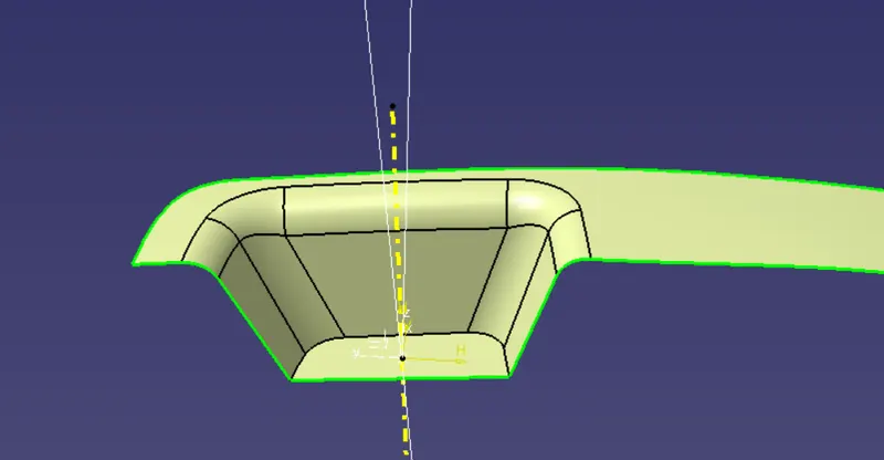
DRAFT ANALYSIS:
- The analyzing of the model should maintain the nominal 3-degree draft angle to the tooling axis.
- Draft should be given to the plastic component to reduce the wear and tear and improve the production quality and accuracy while ejecting the part from the mold cavity.
How to perform the draft analysis
1. Go to insert < analysis< feature draft analysis.
2. Align the tooling axis with a compass.
3. Click on the surface to see whether it is in permissible limit draft values or not.
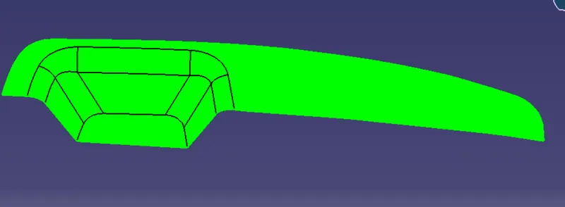
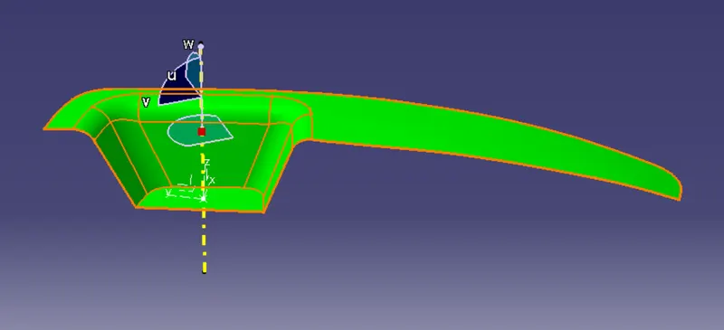
4. The entire surface should be green in colour.
DRAFT ANALYSIS FOR CLASS-A SURFACE:
DRAFT ANALYSIS FOR MODEL:
DESIGNING METHODOLOGY OF CORE AND CAVITY:
- Core and cavity is the perspective vision of injection molding operation to create the components or parts.
CREATION OF CORE BLOCK DESIGN:
- Consider a class A surface.
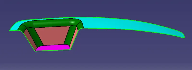
- Extrapolate a class A surface and trim the extrapolated class A surface with class C surface.
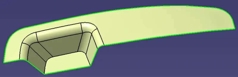
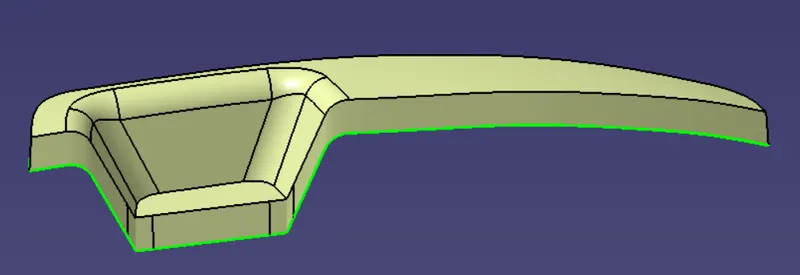
- Take a class B surface of bezel switch and trim with joined or trimmed class A ad class C surface.
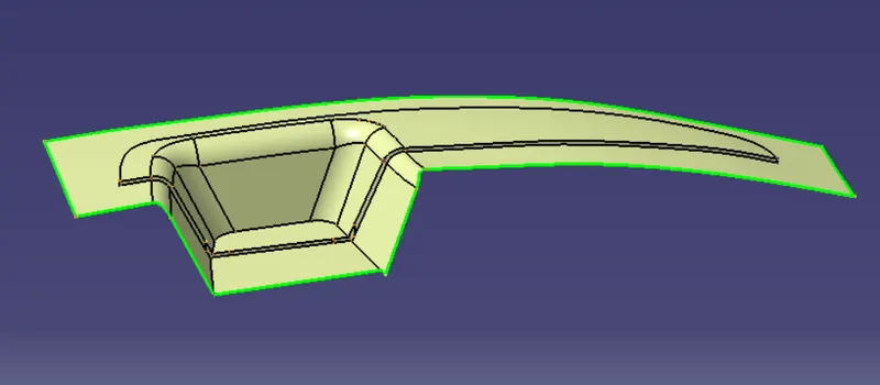
- The output surface structure is called the parting surface with the component area.
- Make the positioned sketch with reference to the XY plane.
- Sketch the rectangle inside the boundary of the output parting surface with the component area.
- Extrude the sketch with tooling direction.
- Fill the top surface of the core block using the surface fill option with reference to the boundary of the extruded surface.
- Join the extruded surface with the filled surface.
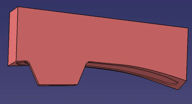
- Trim the joined surface with a parting surface of the component area.
- Get the core block with mold cavity impression at the bottom of the surface.
CAVITY DESIGN BLOCK:
- Take the sketch drawn in the core design as a reference.
- Extrude the sketch with reference to tooling direction.
- Fill the bottom surface of the cavity block using surface fill features with reference to boundary of extruded surface.
- Join the extruded surface with the filled surface.
- Trim the joined surface with a class B surface.
- Get the cavity block.
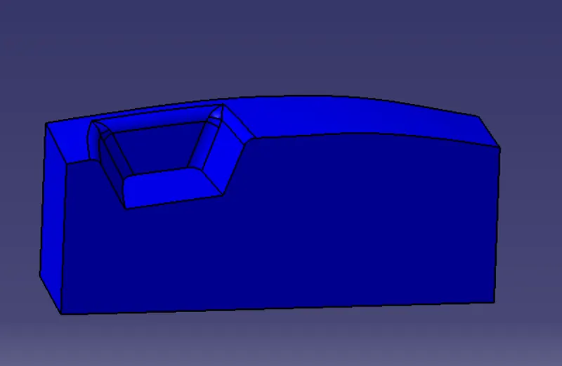
PARTING LINE:
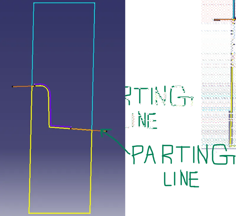
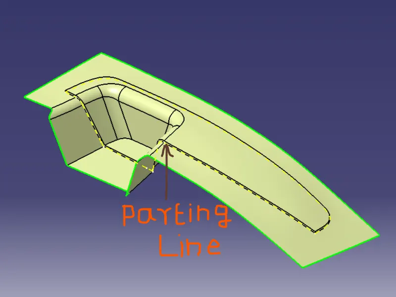
- Parting line is the line of separation on the part where the two halves of the mold meet
- To create the parting line, Extract the external boundary of the connected class C surface with the class B surface.
- Extracted boundary is called a Parting line.
PARTING SURFACE:
- Parting surface is the surface that separates the mold block into two parts.
- These two halves are pressed tightly and form a sealed hollow to avoid melt flow leakage and maintain certain holding pressure, the pressed surface is called the parting surface.
- Generally, parting surfaces are the biggest projection outline of the part.
- The parting surface should be formed by reference of the class B surface without using the reference of the Class A surface to avoid the flash formation on the class A surface, Because the class A surface is an aesthetic outermost visible surface.
PARTING SURFACE DESIGN PRINCIPLES:
- Parting surface design directly affects the product quality, ease of construction, ease of construction, and operation of the injection mold, the mold design is one of the key factors to success.
DESIGN METHODOLOGY OF PARTING SURFACE:
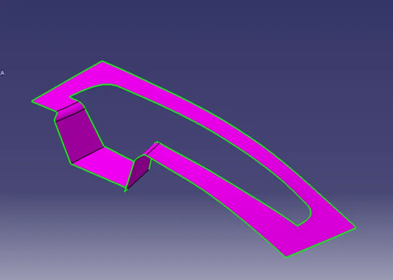
- Split the parting surface with a component area using the parting line.
- Split surface is called a parting surface.
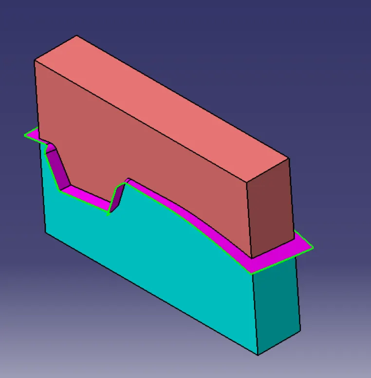
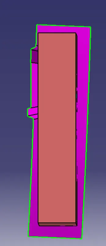
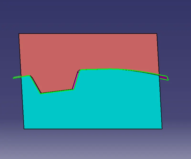
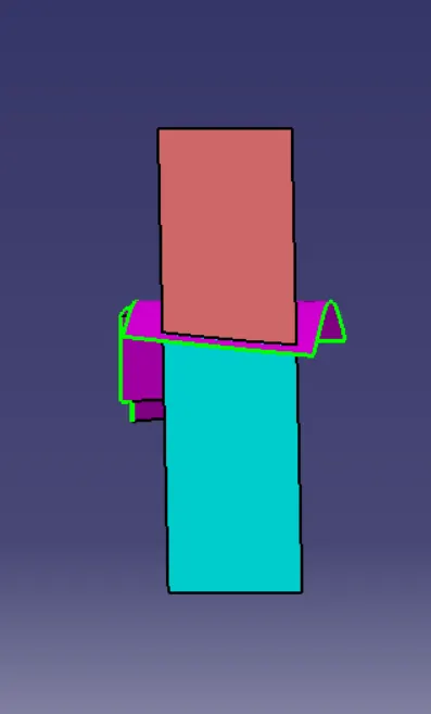
CORE AND CAVITY BLOCK IMAGES:
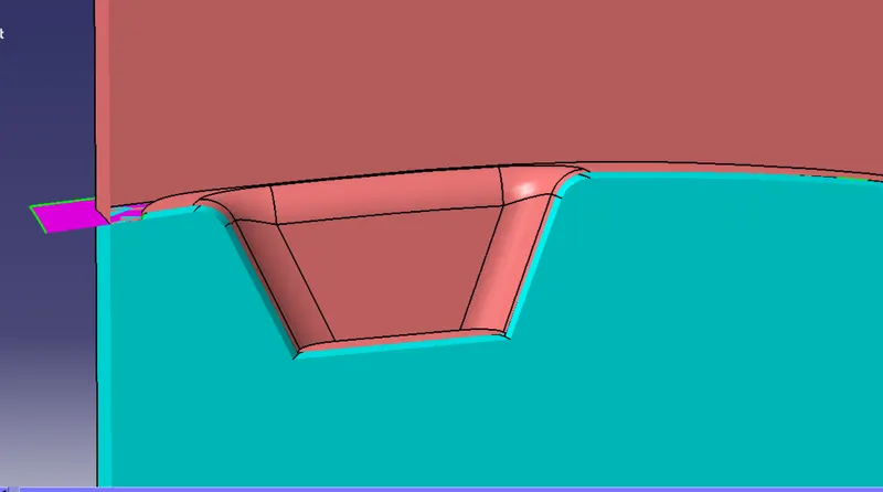
CROSS SECTION IMAGE:
CORE AND CAVITY TRANSLATED IMAGES: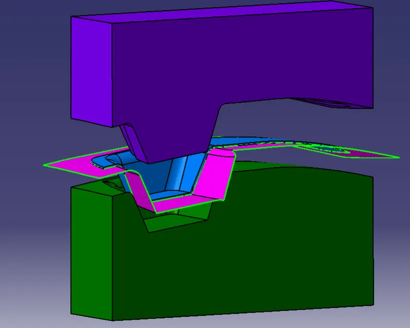
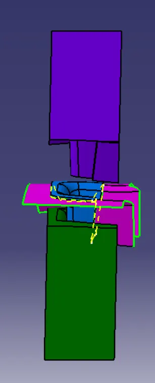
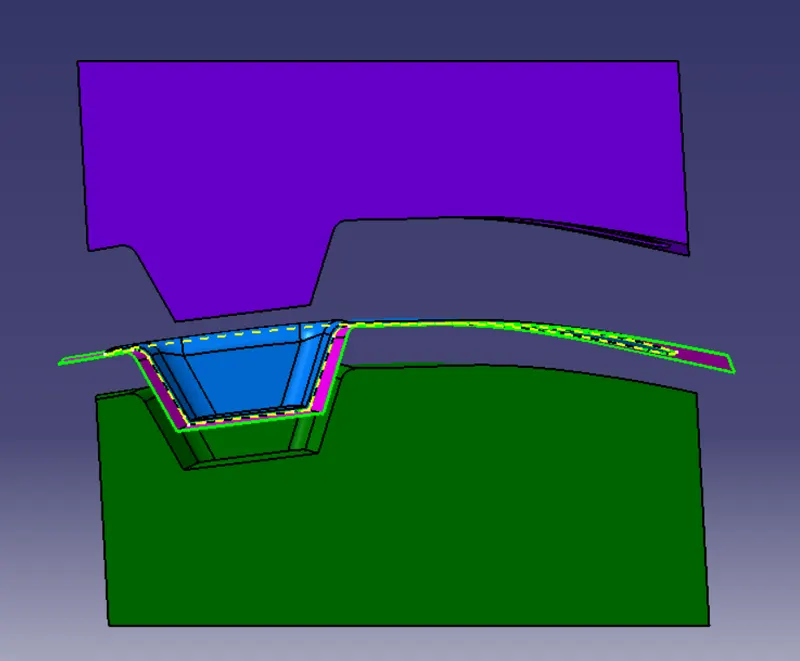
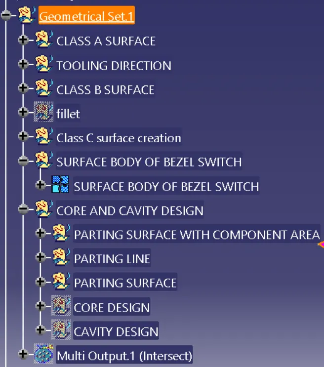
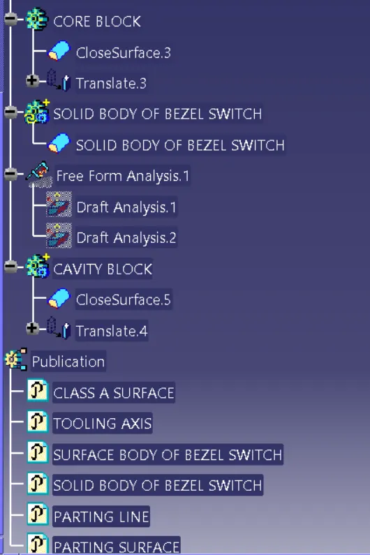
EXPANDED TREE: