Week 8 - Challenge 6 - Core & Cavity Design
Core & Cavity Design
Aim: To create the Core and cavity blocks for the Switch Bezel Component.
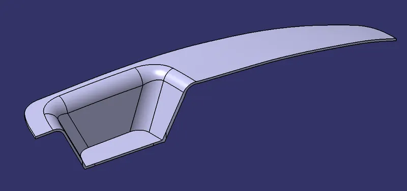
Objective:
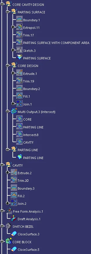
- Ensure Proper Tree Structure
- Geometrical sets should have a proper name based on the sketches present inside of it
- All the sketches should be created under the Geometrical set
- Use the Close Surface feature to make a solid body from the surface.
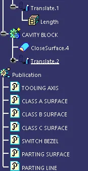
- Publications: Use the publication option and publish the below
- Tooling Axis
- Switch Bezel Solid / Surface body
- Parting Line and Parting Surface
Tooling axis creation :
- To create the tooling axis, we need the proper orientation or view that gives the correct features and draft available in the component.
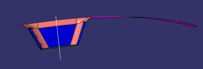
- So here the component view from the Z direction gives the proper view for the tool to see the features present in the geometry.
- To create the tooling axis from the Z direction we need the tooling axis from the other X direction since it gives the draft available at the slanted part.
- The tooling axis is created from the X direction by following the steps
- The base surface is extracted.
- Then the center point is created using the point > on the surface at 0
- At the point created the axis system is created
- After that, switch the model's view to the X direction and create the tooling axis.
Using the intersect in the ZY plane to get the boundary lines.
Then the lines are created along the slant surfaces.
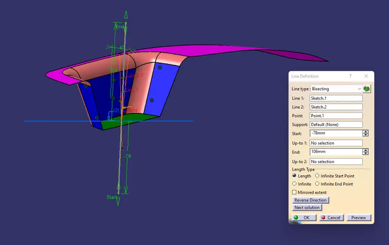
Then these two lines are bisected to get the tooling axis for the X or the final
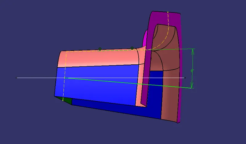
- Next, switch in the Y direction and intersect the switch bezel part in the ZX direction to get the intersecting lines.
- Using the axis center point, a line is drawn in sketch mode and it is constrained at the angle of 4 degrees. (this angle value is an arbitrary value and can be changed to get the final tooling axis that provides a positive draft )
- At last, both the lines are bisected to get the final tooling axis.
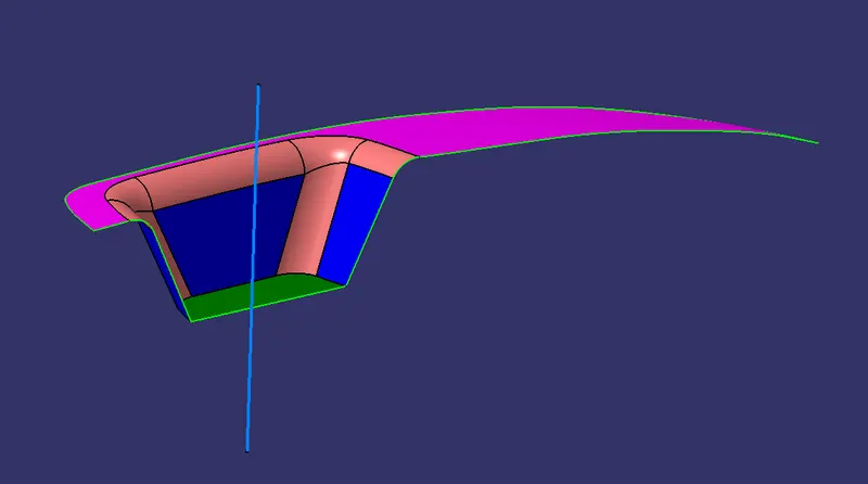
DRAFT ANALYSIS ON SWITCH BEZEL COMPONENT:
- Go to insert> analysis> feature draft analysis
- Align the tooling axis with the compass.
- Click on the surface and see that the surface is within the permissible limit of the draft values.
- The surface should be green and in the column nominal value 3deg given as input. hence the draft analysis on the switch bezel is successfully performed.
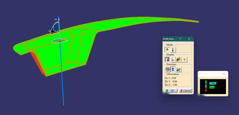
The draft analysis command lets you detect if the part you drafted will be easily removed. This type of analysis is performed based on color ranges identifying zones on the analyzed element where the deviation from the draft direction at any point, corresponds to specified values.
Core and Cavity design
Cavity and core are used in the injection molding process, where the concave part of the mold is the cavity and the convex part is the core. The cavity and core are used in pairs, with the cavity also referred to as the female mold and the core as the male mold.
To create these parts we have to make a parting surface first.
A parting surface is a surface that separates the mold block into two parts – the core and the cavity.
For that, the Class C and Class B surfaces are used.
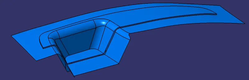
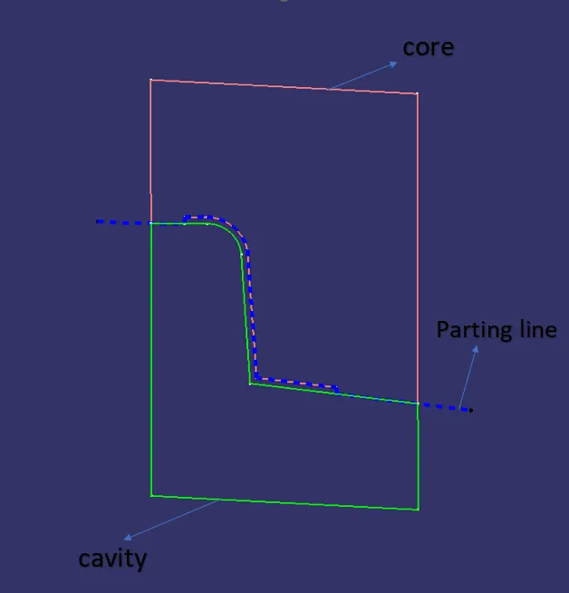
By intersecting the two surfaces class c and class b we get the parting line.
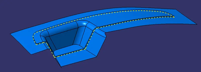
with the parting line, use a split command element to cut as a component area; the cutting element is the parting line.
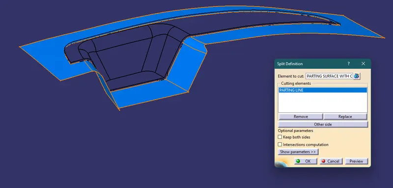
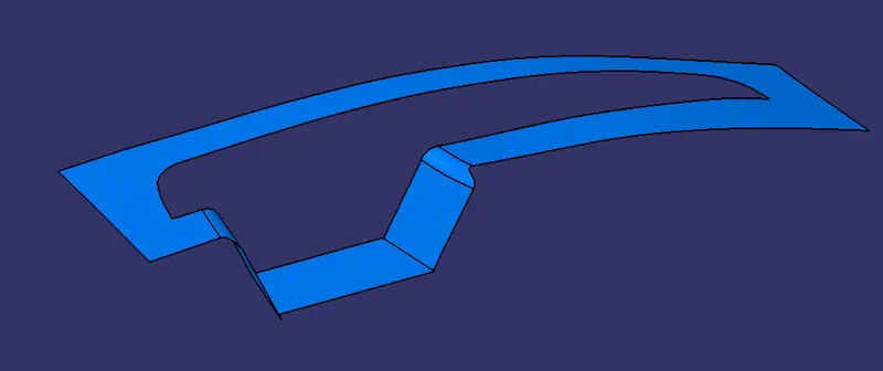
Parting surface:
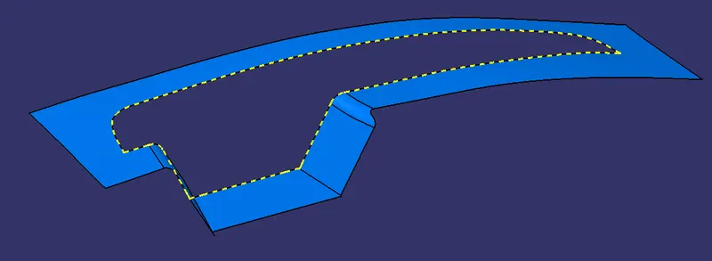
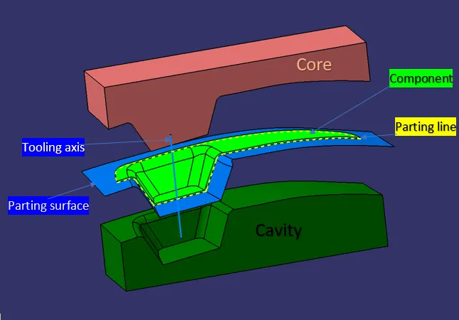
During the injection molding process, the core and cavity are pressed tightly and form a sealed hollow to avoid the melt flow leakage and maintain certain holding pressure the pressured surface is called a parting surface usually, the parting surface is the most considerable projection outline of the part.
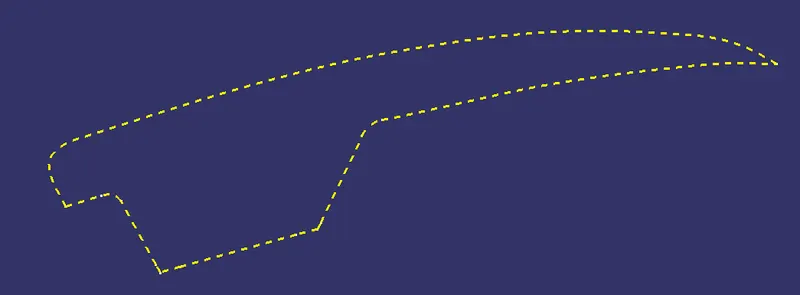
Parting line:
The parting line is an area in which the components and parting surface meet or it is a junction between the core half, cavity half, and parting surface. A parting line is an inevitable part of injection molded products. It manifests itself on injection molded parts as a line that runs the entire perimeter of the part. The parting line which basically known as the intersection between the Class B and C surface.
Parting line and Parting surface
Core and Cavity design:
Core:
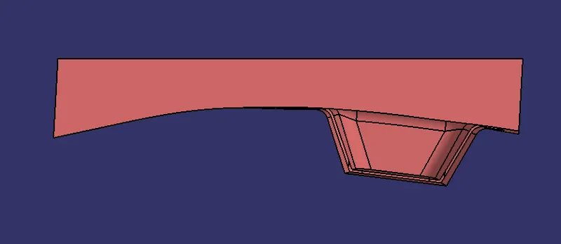
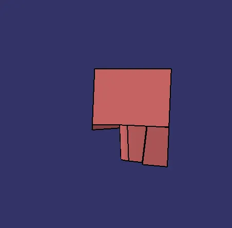
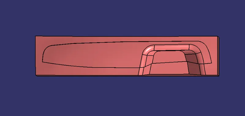
here, The core block is made by drawing the boundary sketch and extruding it along the tooling axis direction followed by the filling and thickening.
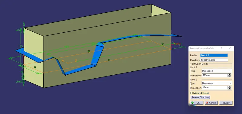
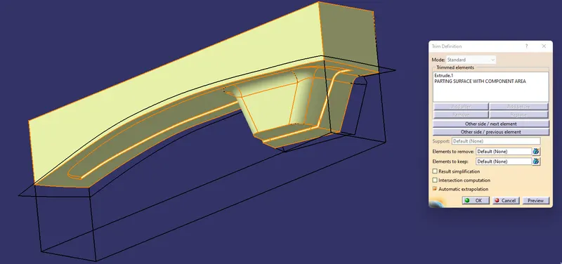
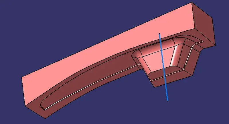
Cavity design:
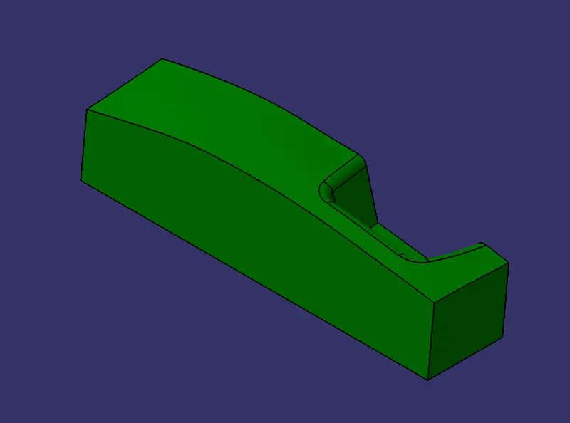
The cavity block is created by first extruding the outer boundary along the tooling direction
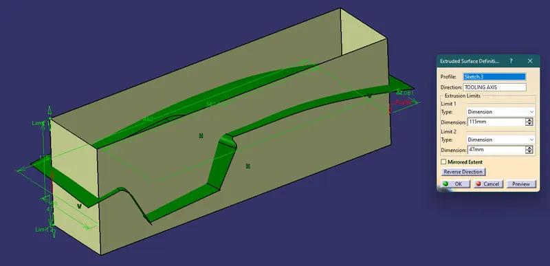
This outer surface is trimmed with the B class surface and then it is filled and thickened.
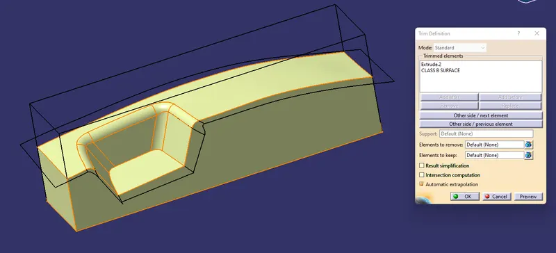
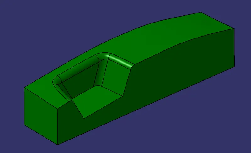
Here intersecting the parting surface, core, and cavity across the ZX plane gives the intersecting line that shows the parting line.
CORE
ISOMETRIC VIEW
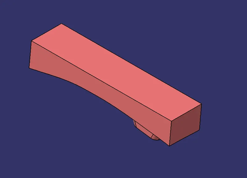
FRONT VIEW
SIDE VIEW
TOP VIEW
CAVITY
ISOMETRIC VIEW
FRONT VIEW
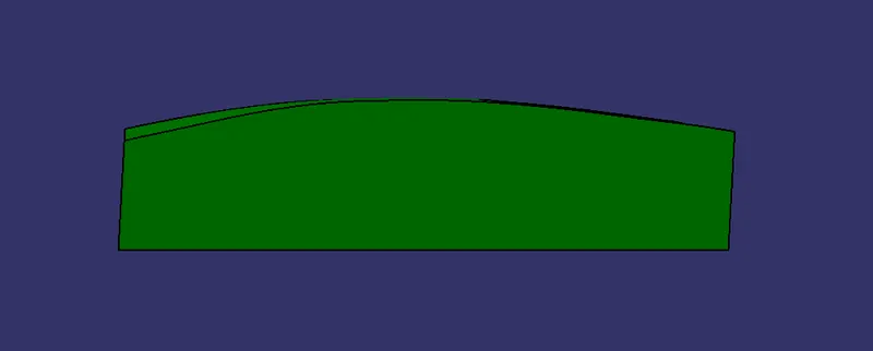
SIDE VIEW
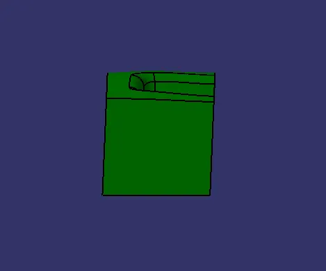
TOP VIEW
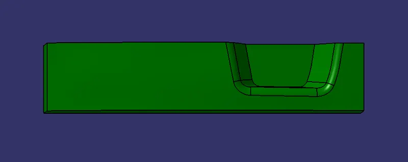
The image shows a detailed understanding of the core, cavity, parting surface, parting line tooling axis, and the component.
FEATURE TREE:
 .
.
CONCLUSION:
The Core and cavity blocks for the switch bezel component are created