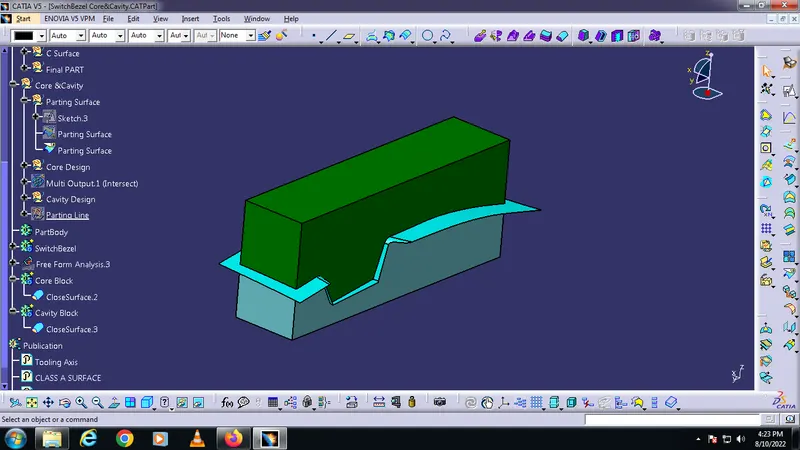
Week 8 - Challenge 6 - Core & Cavity Design
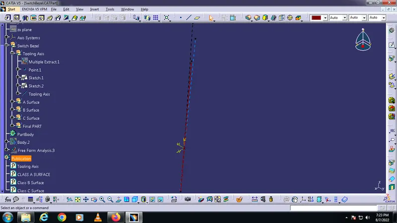
Tooling Axis -
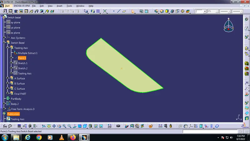
- Creating a point on the base surface
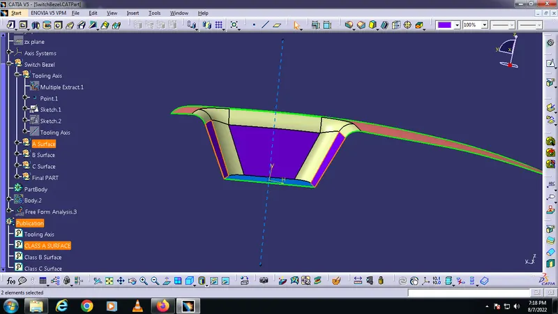
- Then creating a dummy axis along Two side planes
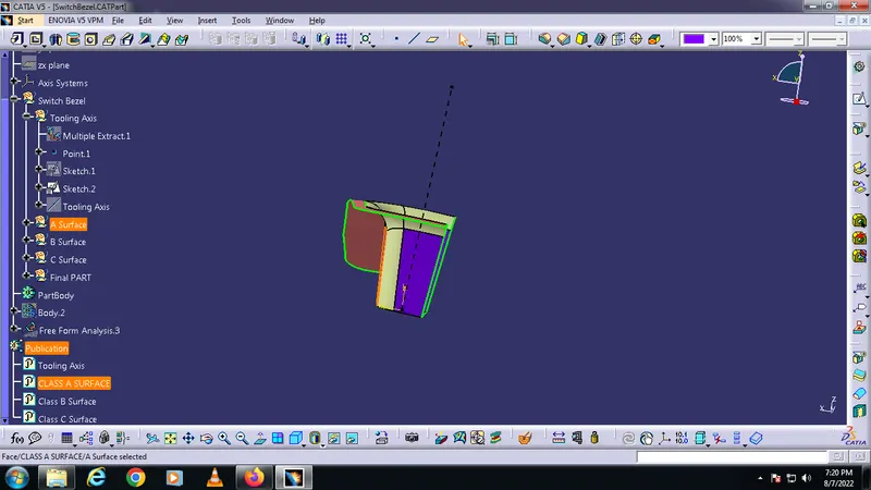
- Creating another axis along sine plane
- Creating the tooling axis by bisecting the two dummy axis
Draft Analysis -
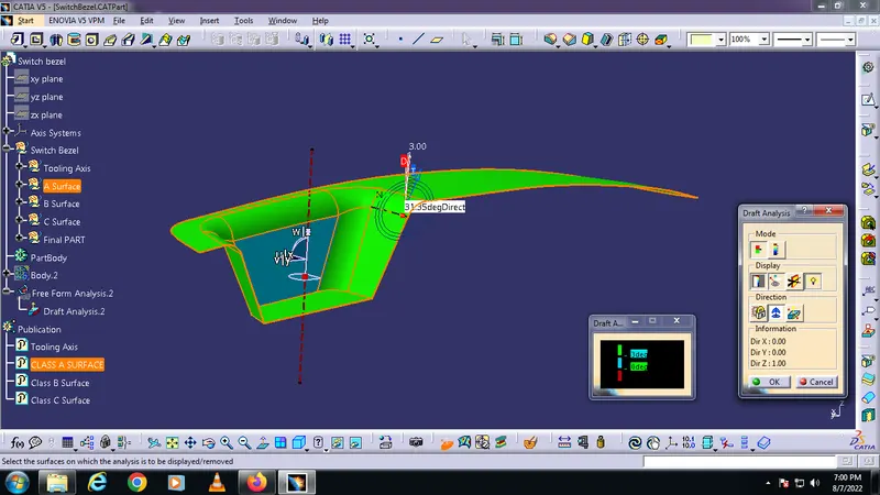
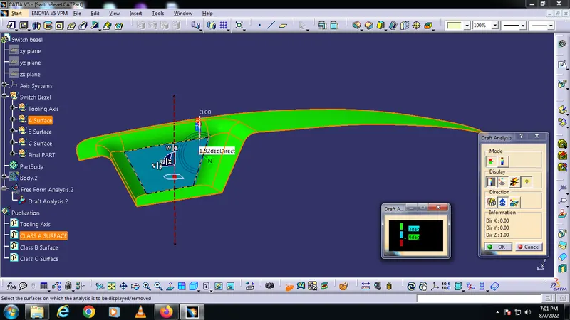
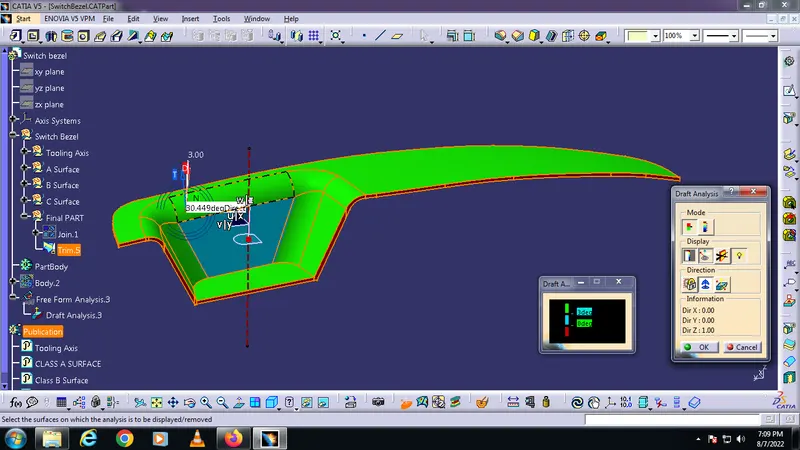
To do Draft Analysis, go to tools > analysis > Feature Draft Analysis. This tool has three groups of options namely; mode, display, and direction. First, the second icon from the direction group is selected and the red dot in the compass is clicked and dragged to the part to be drafted. The line in the dragged element is matched with the tooling axis and it is locked using the first icon in the direction group. It will define the tooling axis direction and lock it. Then click the base bracket. It will turn green or with green and red based on the draft angles. Minimum draft angle is set to 3. If the portion has enough draft angle, it will show it in green.
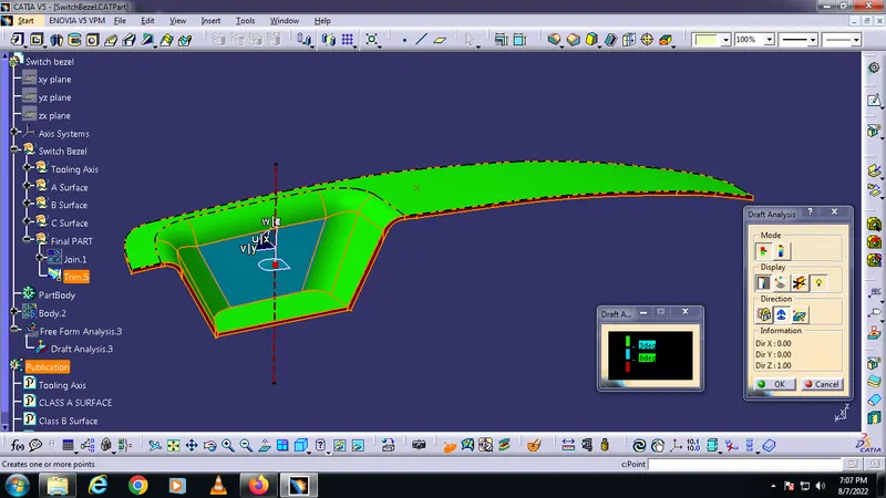
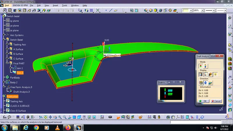
Draft analysis report for the given Class-A surface -
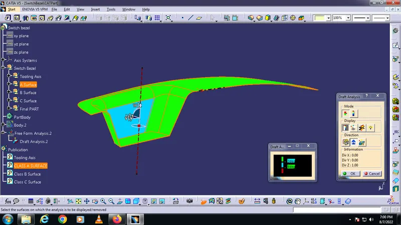
Draft analysis report for the final plastic component -
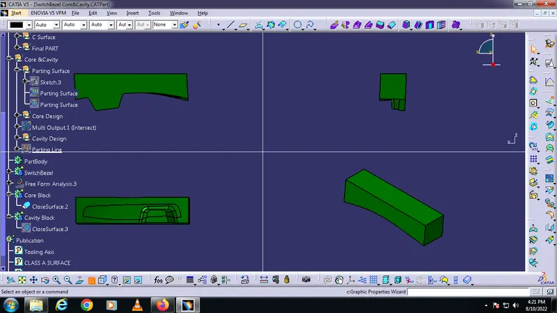
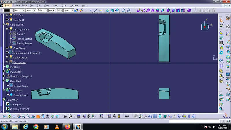
The core and cavity blocks in various orientations (Isometric, Front, Side, and Top View) -
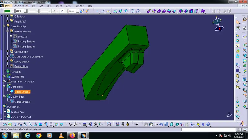
Core
Cavity
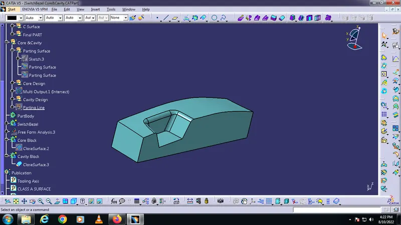
Core & Cavity with Parting Surface