Week 8 - Challenge 5 - Door Trim Lower
NOTE: I have Attached the Report, Photos and CADpart in the Attachment
Week 8 - Challenge 5 - Door Trim
AIM:
To Create the Bumper Design Plastic component through the given Class-A surface. Create the tooling axis for the given Class-A Surface by meeting the requirements of the draft angle and at the end perform the Draft analysis on the model.
OBJECTIVE:
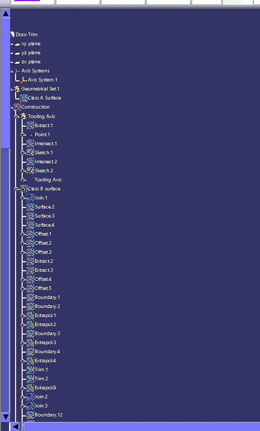
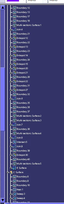
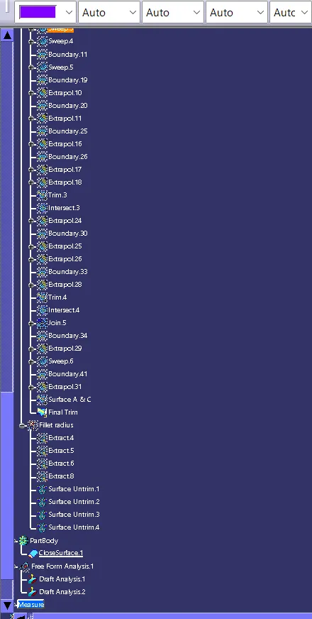
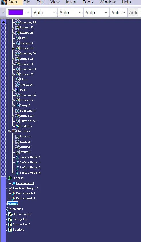
- Tree Structure
- Ensure Proper Tree Structure
- Geometrical sets should have a proper name based on the sketches present inside of it
- All the sketches should be created under the Geometrical set
- Use the Close Surface feature to make a solid body from the surface.
- Publications: Use the publication option and publish the below
- Tooling Axis
- Class A, B, and C surface
- Report
- A detailed report should be done explaining the draft analysis and the tooling axis creation.
- An explanation should be given on the way of creating the tooling axis, particularly the Bisecting method.
SOFTWARE USED : CATIA
INPUT:
CAD DATA is downloaded and Opened with CATIA.
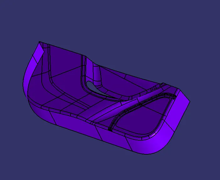
TOOLING AXIS:
- Tooling axis is defined as such all the features of the part can be manufactured easily. so here we followed the below steps to create the tooling axis.
- Extract a face and create a center point and a axis on it
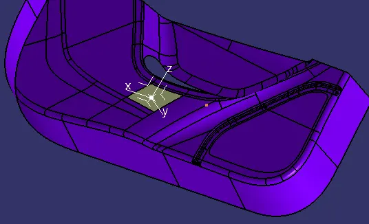
- Create a intersection with ZY axis and create a line bisecting the last edges
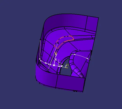
- Create a intersection with XY axis and create a line bisecting the last edges
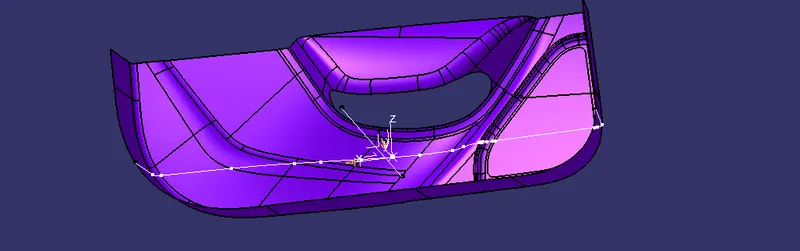
- Create a bisecting line with the two sketch lines. this is the tooling axis
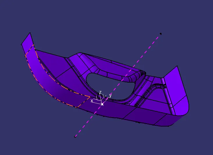
DRAFT ANALYSIS:
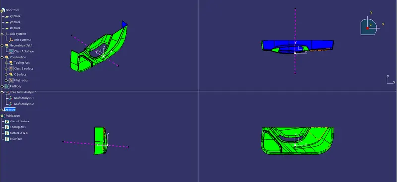
- Draft is done on the Class A surface.
- Change it to material in customise view.
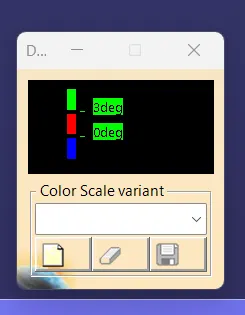
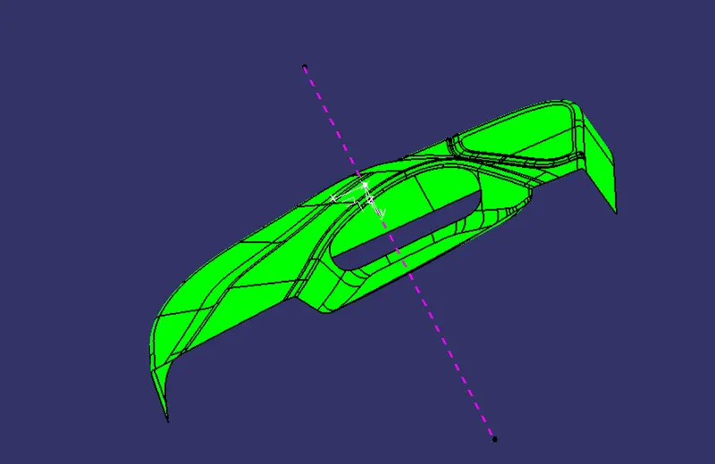
- Click the Draft analysis tool and click the surface and align the compass to tooling axis.
- 3 degree is the clearing angle
- So here is photo of cleared (Green) draft.
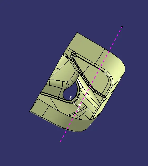
B SURFACE:
- B surface is created by using the given Class A surface
- Join all the faces except the fillets
- So we get separate 5 parts
- And all are offseted 2.5mm beneath the A surface
- take boundry and Extrapolate the edges
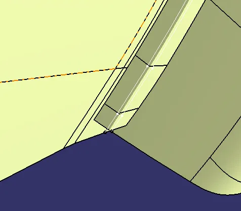
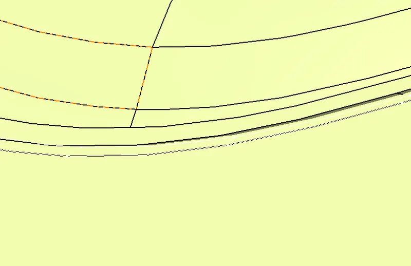
- Trim the edges.
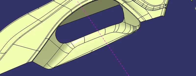
- Join all the faces so we form the B surface
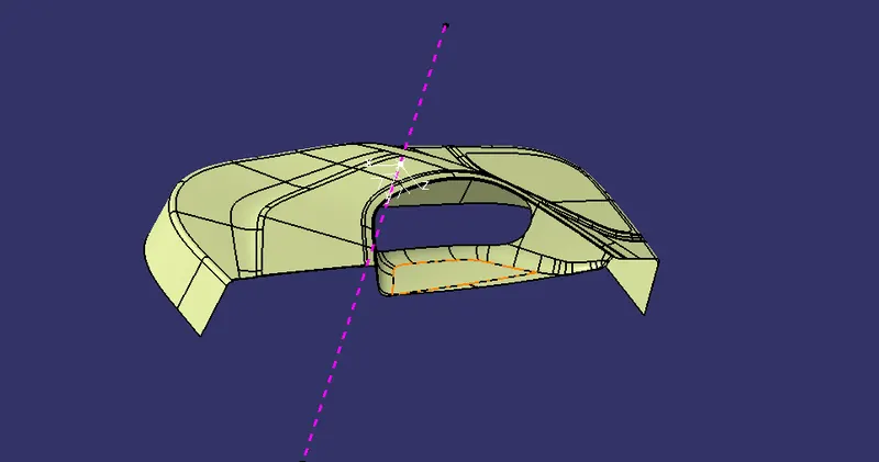
C SURFACE:
- Class A boundry is taken.
- Boundry of the A is taken.
- Sweep is used to form the C surface.
- Be aware of the draft limit and make the sweep accordingly
- Join the segmented parts to get a whole C surface
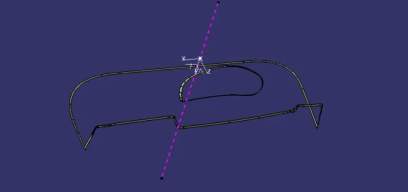
FINAL PART
- Surface C and A is joined.
- Surface B is trimmed with C & A.
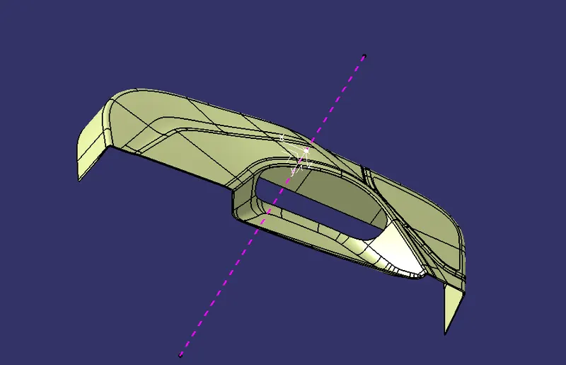
- Closed Body is created
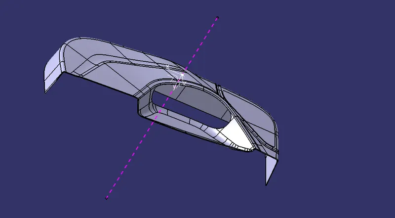
DRAFT ANALYSIS:
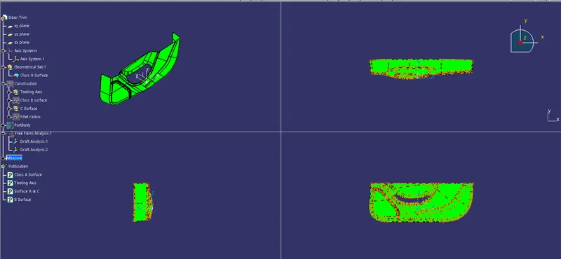
- Draft is done on the Final Part.
- Change it to material in customise view.
- Click the Draft analysis tool and click the surface and align the compass to tooling axis.
- 3 degree is the clearing angle
- So here is photo of cleared (Green) draft.
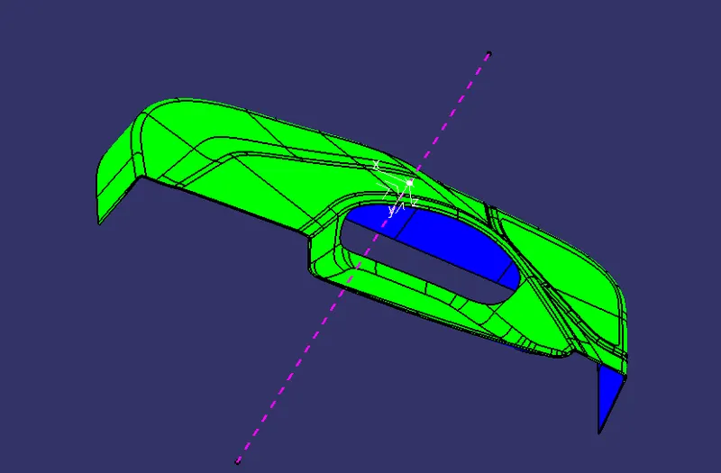
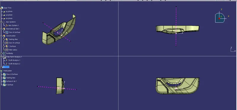
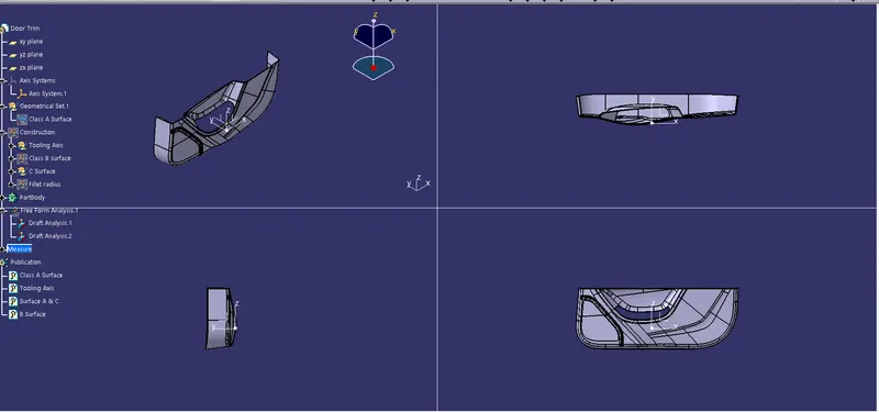
Here are the photos of Door trim
Color varient