Week 8 - Challenge 5 - Core & Cavity Design
Aim: Creating the Core and cavity blocks for the Switch Bezel.
Description:
Draft Analysis:
Draft is the angle in which the part is tapered for easy ejection from core and cavity block.
Draft analysis is a technique used to analyze whether the drafted CAD model is manufacturable with the given draft conditions. Tooling axis (the direction in which the mold is ejected) is provided, so that there should be a smooth ejection of the surface/part from Core-Cavity block.
Tooling axis creation:
1. Extracting the surface from class A-Surface and creating point on that surface.
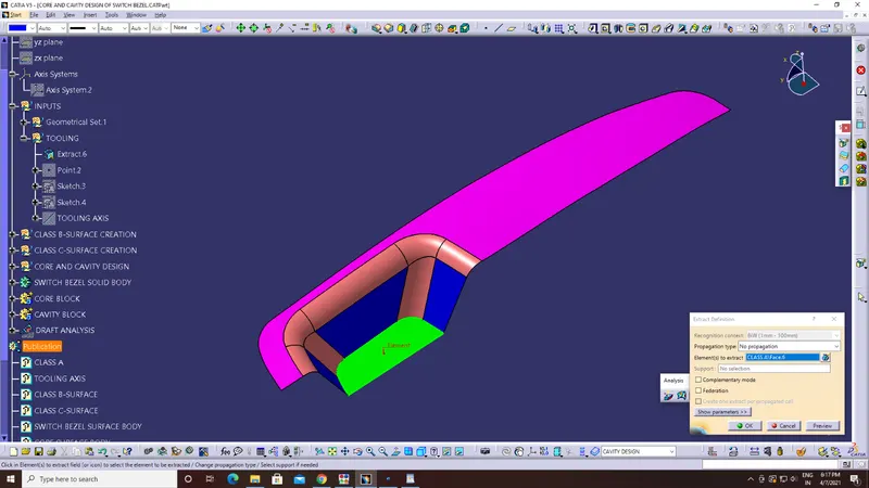
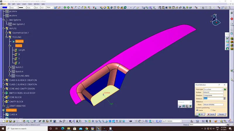
2. Creating axis system on the point.
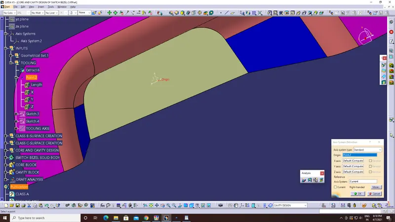
Tooling axis in one direction:
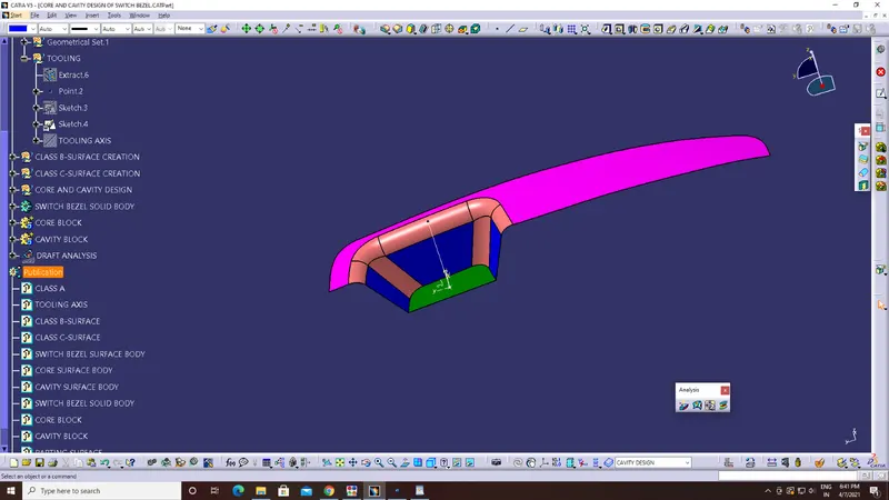
1. Select a proper plane and create sketch for tooling axis. Now, using 3D intersect trace the intersect the curve and turn it to construction line.
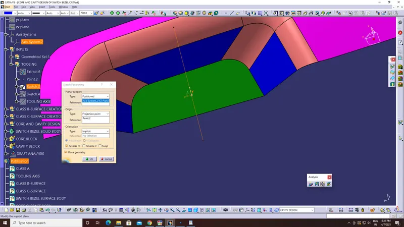
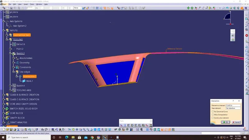
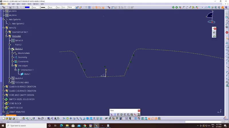
2. Draw two new lines on the inclined curves and then using the bisecting option create a dummy tooling axis.
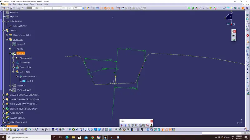
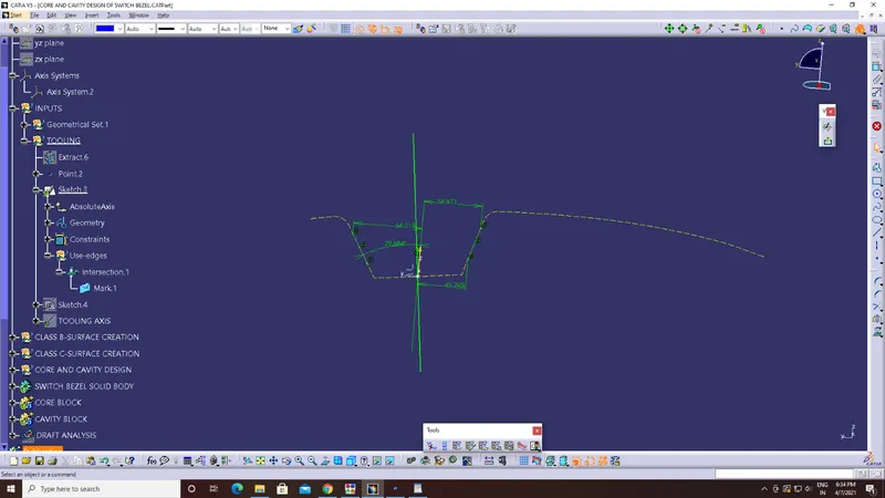
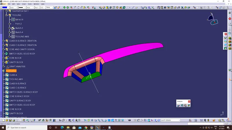
Tooling axis in other direction:
1. Select a proper plane and create sketch for tooling axis. Now, using 3D intersect trace the intersect the curve and turn it to construction line.
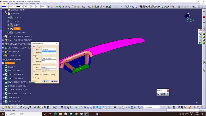
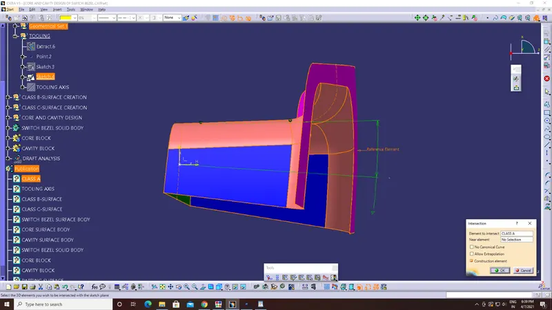
2. Draw a new line on the inclined curve and then draw another line at 50angles. This will be the second dummy tooling axis.
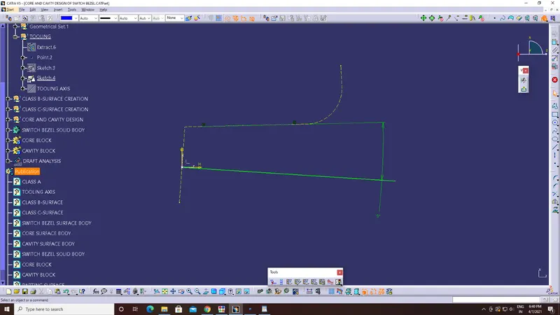
Main tooling axis:
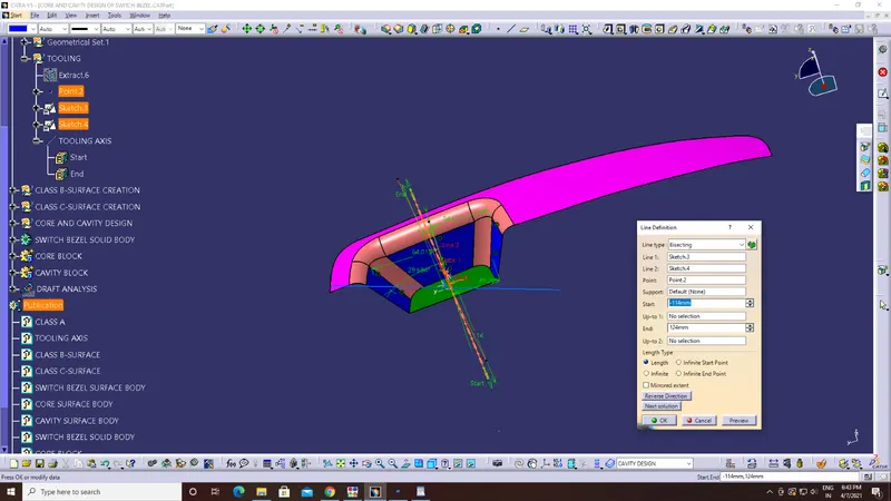
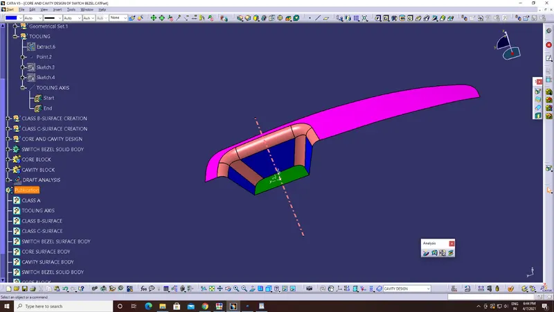
Creating a line by bisecting the two dummy tooling axes, the resulting line will be main tooling axis.
Parting surface creation:
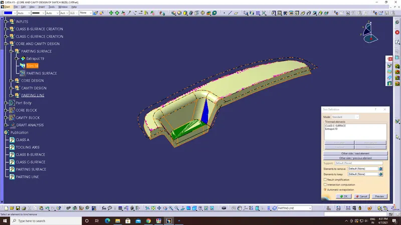
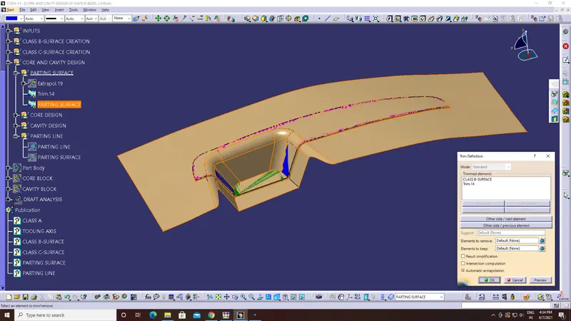
1. Extrapolating the Class A-surface for about 15mm in all directions, so that this can easily trimmed with the ‘Trim. 14’.
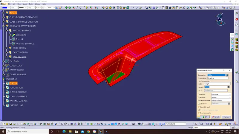
2. Trim the extrapolated part with the Trim.14 and the resulting surface is the parting surface.
Core design:
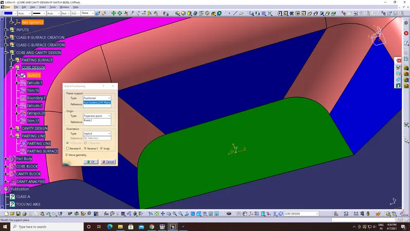
1. Plane XY is selected and the direction the axis for 2D sketchisswapped according to the requirement.
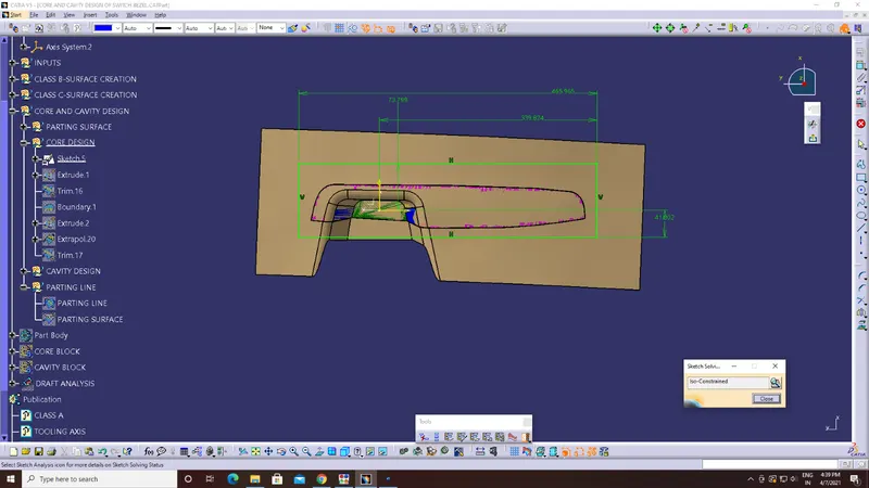
2. Creating a rectangular sketch for core block and Iso-constraining the sketch.
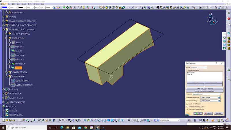
3. Extruding the sketch along Tooling axis and trimming it with Parting surface.
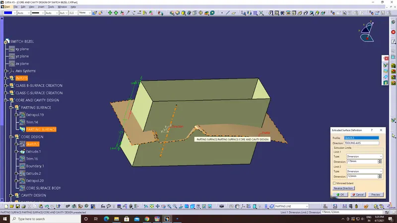
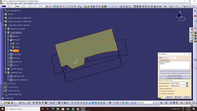
4. Extracting an edge at the top of extrude using ‘Boundary’ option and extruding it and the extrapolating in all direction for few mm.
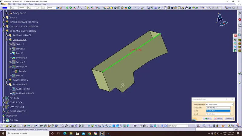
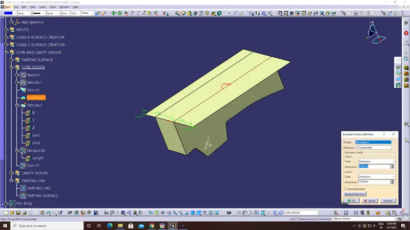
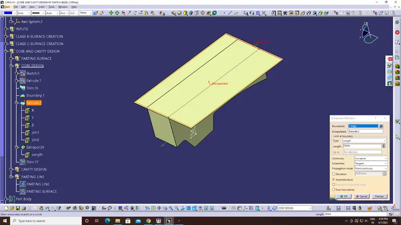
5. Trim it with bottom hollow portion of core surface (Trim.16)
Creating Solid Core body from Core Surface body:
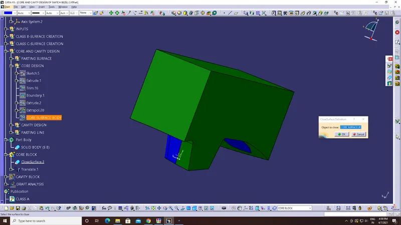
1. Changing to part design window and using ‘Close surface’ from surface-based features. Selecting core surface body as object to close.
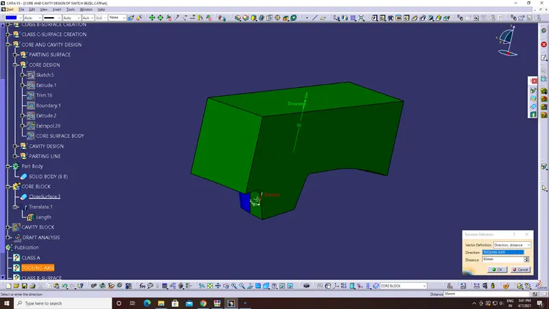
2. Translate to certain distance for clear observation.
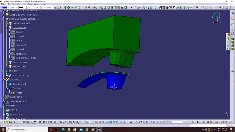
Core in different orientation:
1. Isometric View
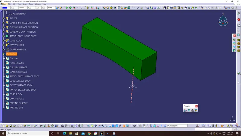
2. Front View
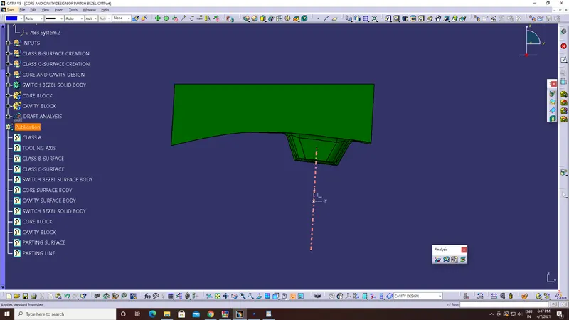
3. Right View
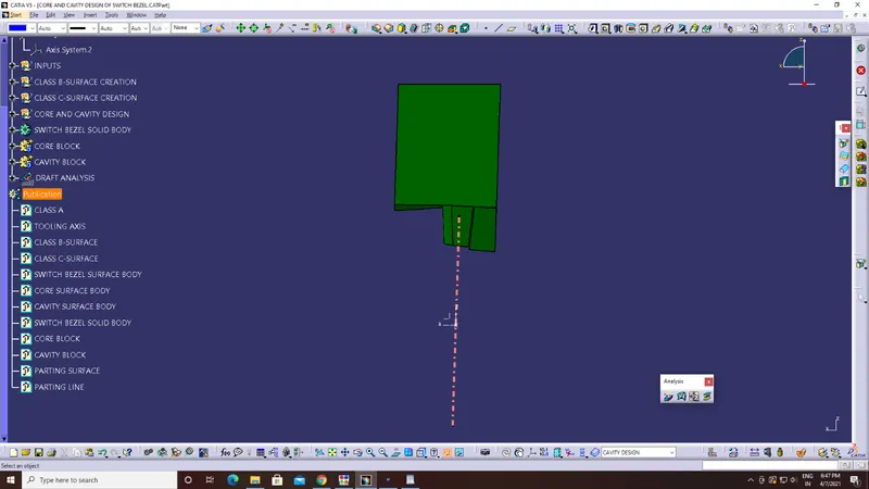
4. Left View
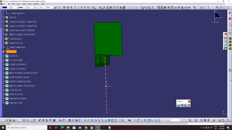
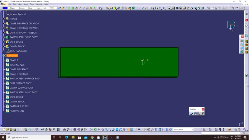
5. Top View
Cavity creation:
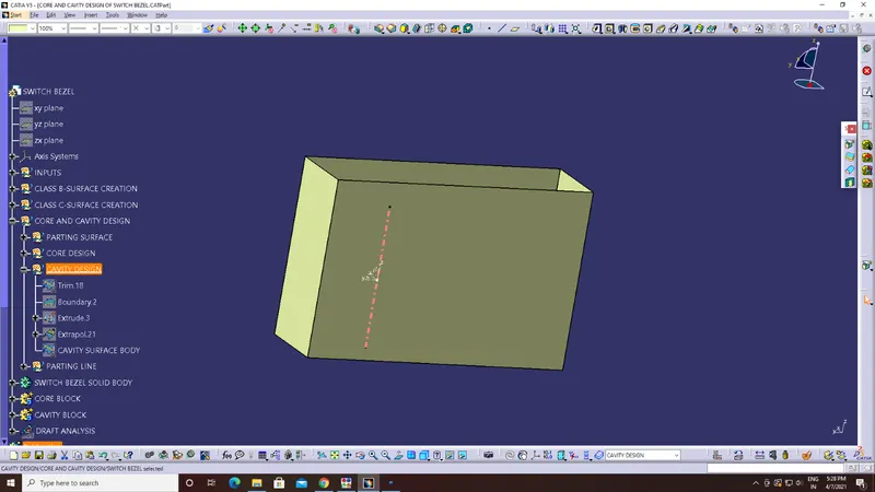
1. Considering the rectangular extrude surface and trimming it with Class B-Surface.
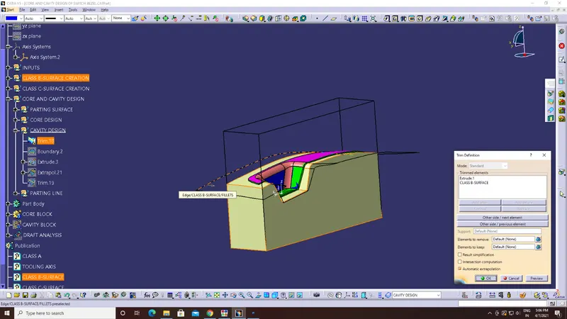
2. Extracting an edge at the top of extrude using ‘Boundary’ option and extruding it and the extrapolating in all direction for few mm.
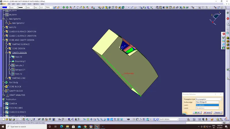
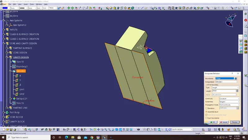
3. Trim it with top hollow portion of core surface (Trim.18)
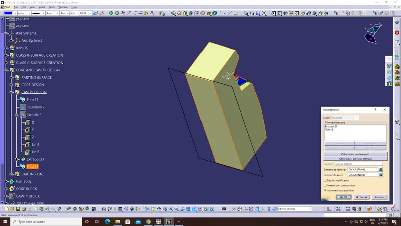
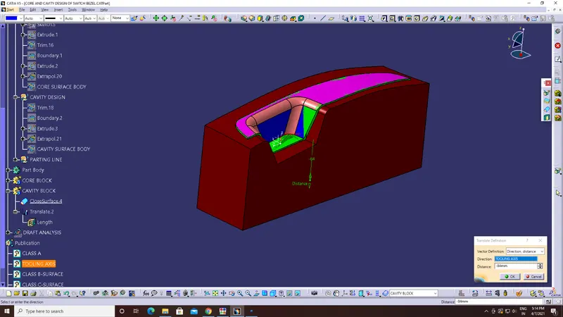
Creating Solid Core body from Core Surface body:
1. Changing to part design window and using ‘Close surface’ from surface-based features. Selecting cavity surface body as object to close.
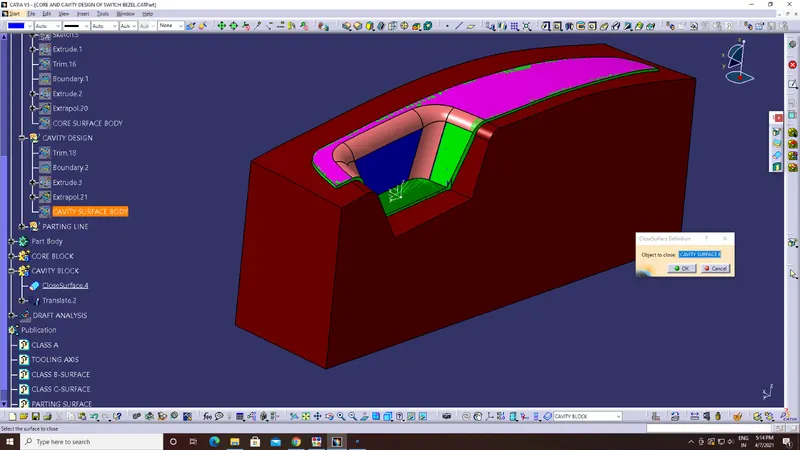
2. Translate to certain distance for clear observation.
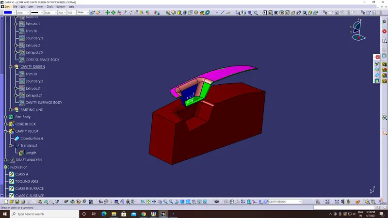
Cavity in different orientation:
1. Isometric View
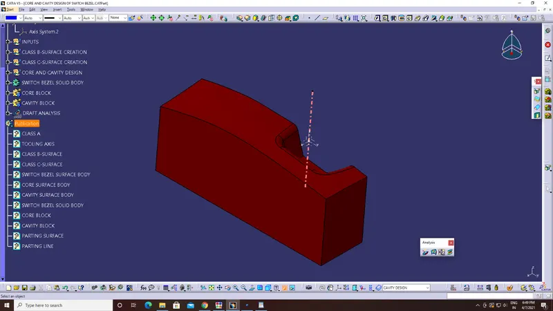
2. Front View
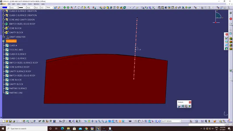
3. Right View
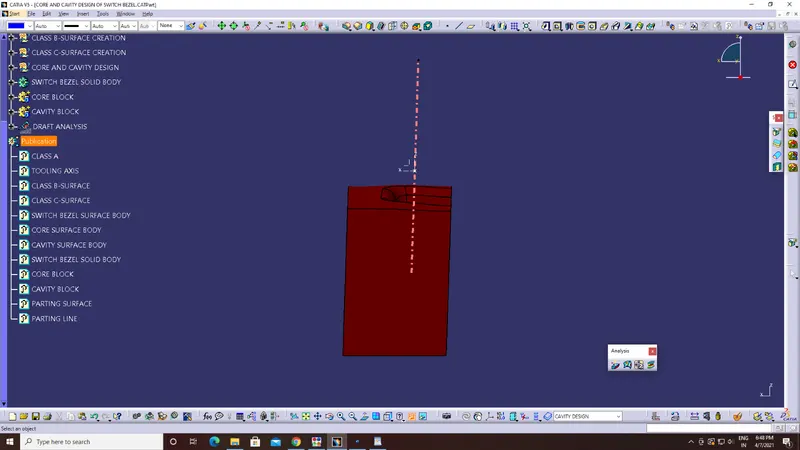
4. Left View
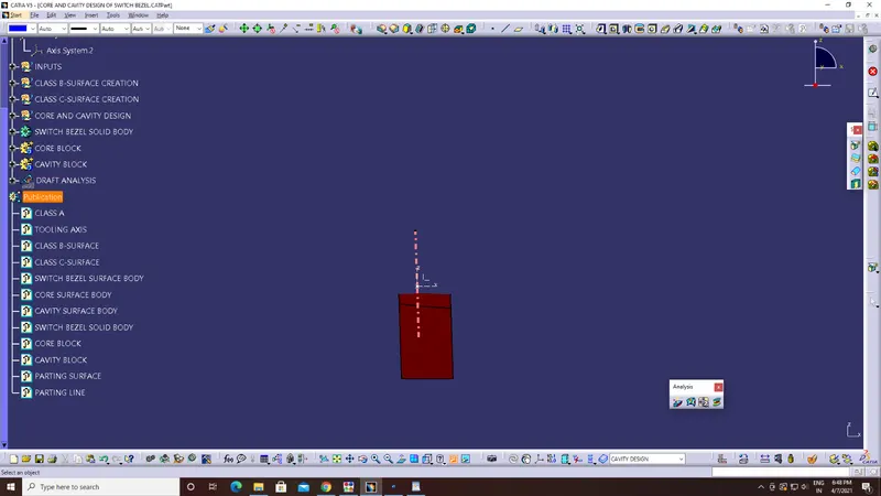
5. Top View
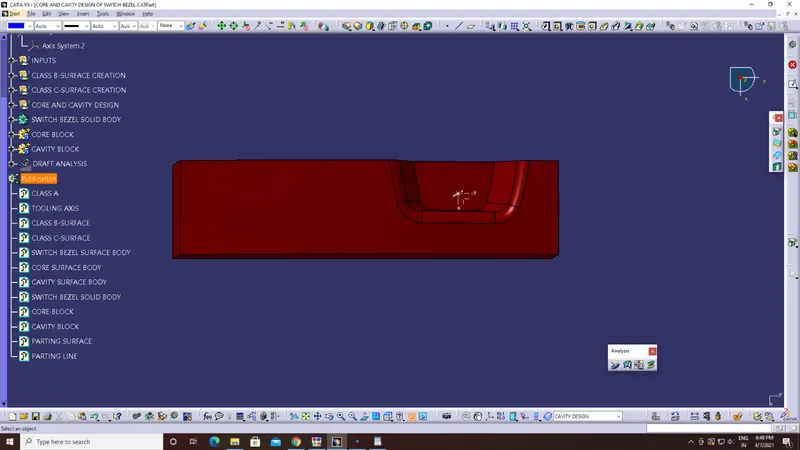
Parting line creation:
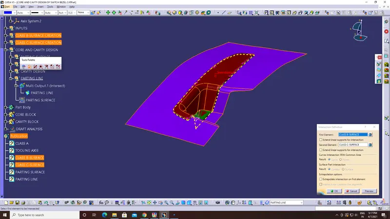
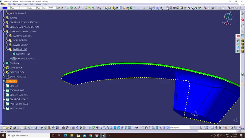
Intersect Class C and B surface the resulting line is parting line. The yellow color line is parting line.
Steps involved in DRAFT ANALYSIS on Class A-Surface:
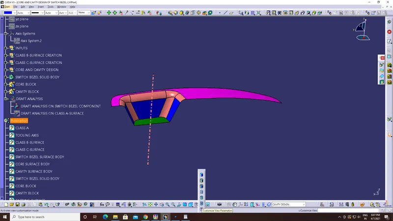
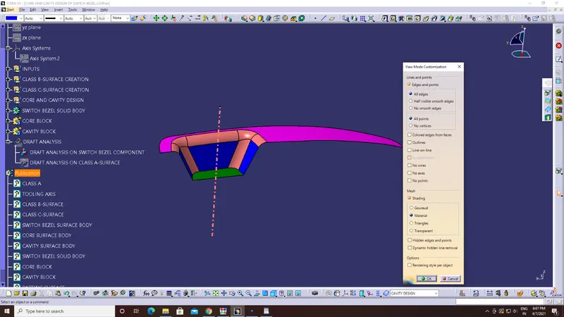
1. Select 'Customize view parameters' from the 'View mode' and choose 'Materials'.
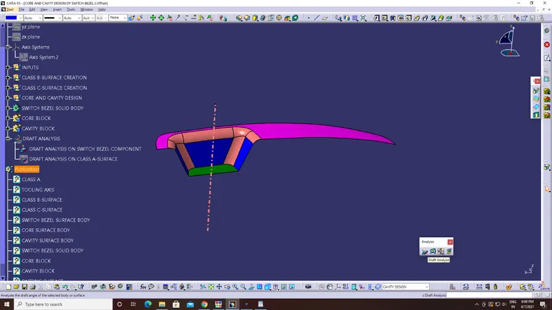
2. Select 'Feature Draft Analysis' from the 'Analysis toolbar'.
3. Now, holding the red-dot, which is on the compass (present on Top-right corner of the window) align with the Tooling axis and lock it.
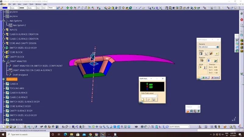
4. Set the Minimum draft angle (3 degree for plastic components) in 'Draft Analysis' dialog box (which has color bands).
5. Choose 'Class A-Surface' as element in 'Draft Analysis' dialog box or just click on the surface.
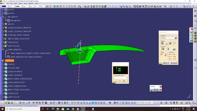
6. After selecting if the color changes to,
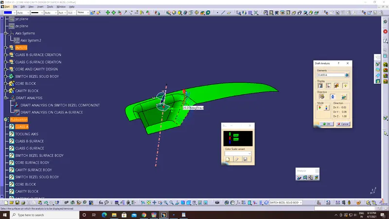
a. Green, then the draft of the Part has minimum draft angle of 3 degree.
b. Red, then the draft angle of the part lies between 0-3 degree.
c. Blue, then the draft angle of the part is less than 0 degree.
7. By choosing 'Analyse under running point' from 'Analysis toolbar' we can check the draft angle at any point on the surface just by moving the pin.
Draft analysis on Solid component:
1. Select 'Customize view parameters' from the 'View mode' and choose 'Materials'.
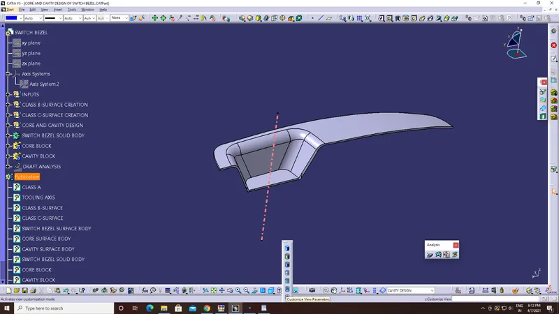
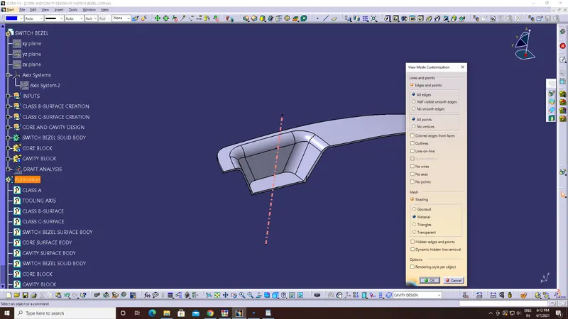
2. Select 'Feature Draft Analysis' from the 'Analysis toolbar'.
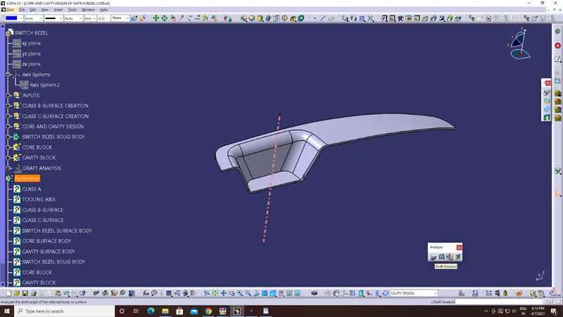
3. Now, holding the red-dot, which is on the compass (present on Top-right corner of the window) align with the Tooling axis and lock it.
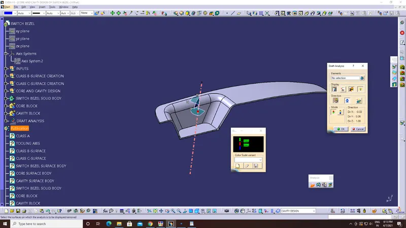
4. Set the Minimum draft angle (3 degree for plastic components) in 'Draft Analysis' dialog box (which has color bands).
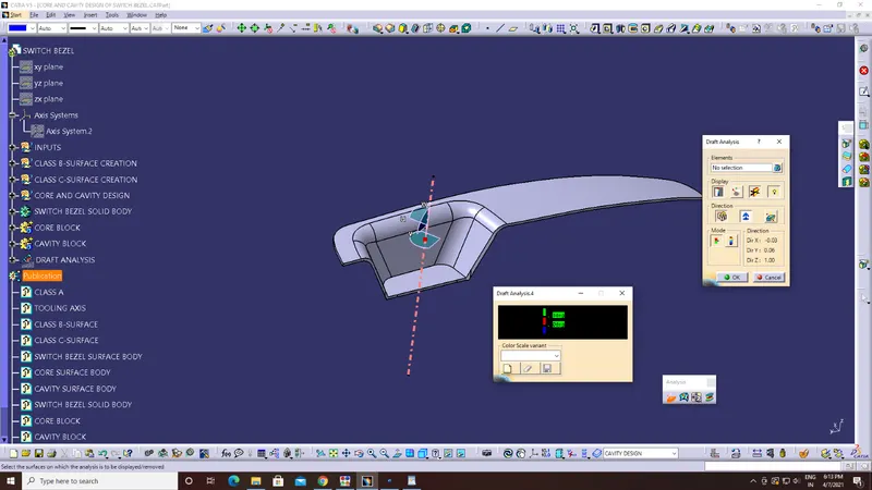
5. Choose 'Class A-Surface' as element in 'Draft Analysis' dialog box or just click on the surface.
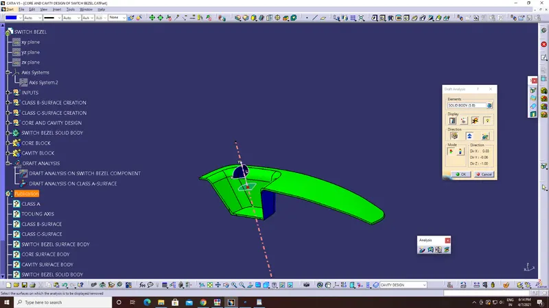
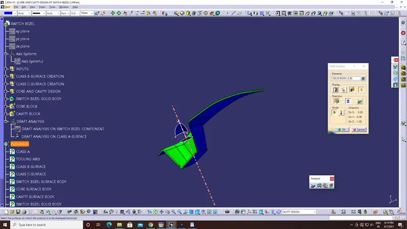
6. After selecting if the color changes to,
a. Green, then the draft of the Part has minimum draft angle of 3 degree.
b. Red, then the draft angle of the part lies between 0-3 degree.
c. Blue, then the draft angle of the part is less than 0 degree.
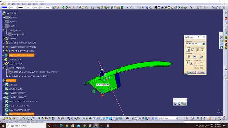
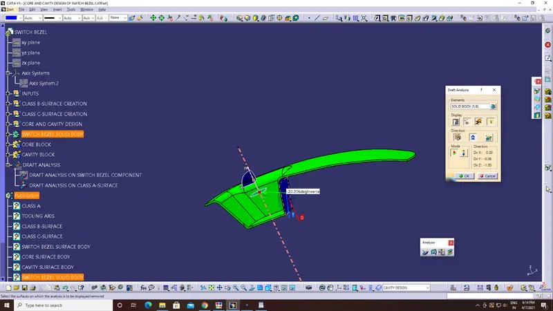
7. By choosing 'Analyse under running point' from 'Analysis toolbar' we can check the draft angle at any point on the surface just by moving the pin.
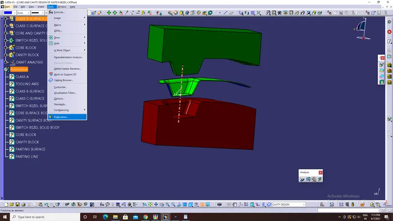
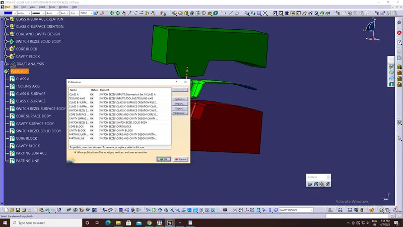
Publication of few components:
Conclusion: Core and Cavity blocks for the switch bezel component are created. Draft analysis is performed on both Class A-Surface and solid component and the draft conditions are satisfied for both.