Week 8 - Challenge 5 - Core & Cavity Design
Automotive Plastic Design using CATIA V5
AIM: To Create the Core and cavity blocks for the switch bezel designed in the earlier challenge.
PROCEDURE:
- First import the surface or the CLASS A model to the CATIA V5.
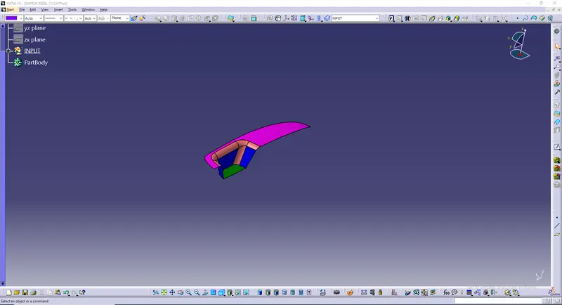
- As the switch bezel is a surface model we have to open it in the GENERATIVE SHAPE DESIGN which is observed in START << SHAPES.
- We have to check the Connectivity of the Class A surface which we have uploded.
- Ensure that there are no gaps between the surfaces on the class a surface.
- Create a point on the class A surface.
- Create a axis system on the class A surface by using the point.
- Now we have to create a tooling axis for the Class a surface. for that we have first create a new geometrical set named tooling axis.
- After creating the Geometrical set, we have to use create a sketch and intersect the model and draw two lines and bisect them to get the Tooling axis.
- Finally we get the tooling axis.
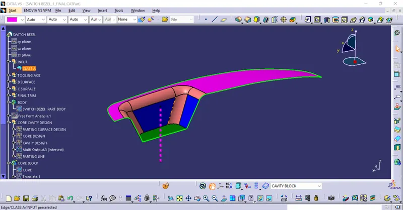
- Publish the Class A surface and the Tooling axis.
- Now we have to create the Class B surface.By using then class A surface we have to create the b surface by using commands like extract,un trim, and extrapolate
- Finally, apply the fillets to the B surface by measuring the fillets on the class A surface. and the class B surface is obtained.
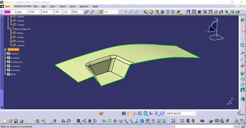
- Now we have to create the Class C surface
- Use Multi extract command and select the edges from class A surface.
- Use sweep command and select Draft angle and direction.
- Smooth the class C surface.
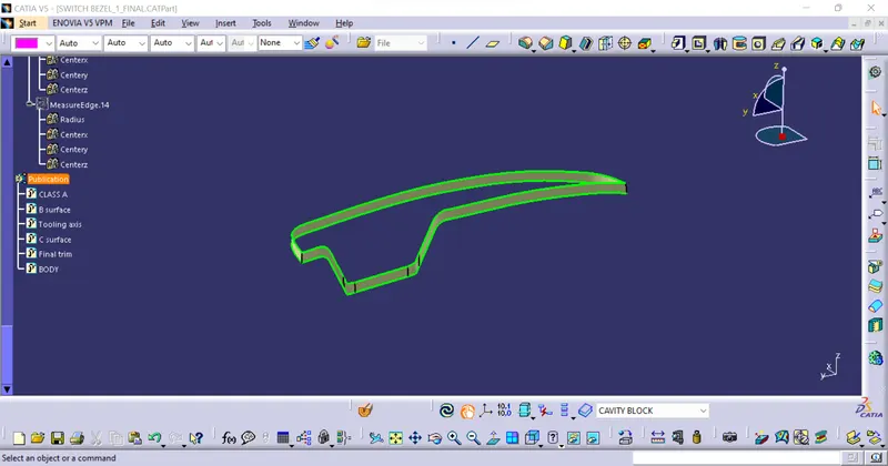
- Now we have all the 3 surfaces ."I had some problem in boundaries so I expoliated the class A surfaces and fixed the problem"
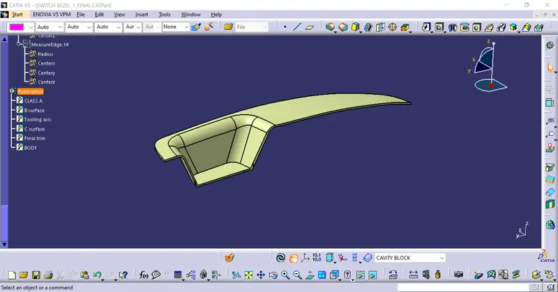
- create a closed surface od the model.
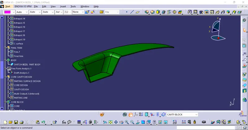
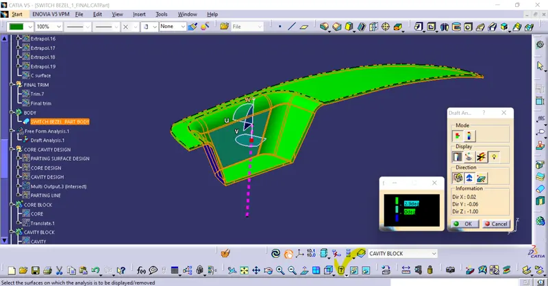
- Now we have to do the draft analysis on the model but before that set the viewing mood to material mood.
- Now, go to draft analysis,click in the compass option in direction and bring it to the tooling axis and lock the compass.
- Give the draft angle mim and max).
- Finally the draft analysis is performed on the model.
- After the draft analysis is done in the body we have to create the core and cavity for that we nned to first create a parting surface
- First create a new geometrical set and take the class A surface and class C surface and join them together.After that trim the new surface with the class B surface.
- Finally we will have the parting surface with the component Area.
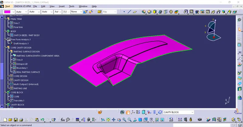
- If we want the actually parting surface. Joined ClassA and Class C surface and then intersect them both and split them with the curve which we got by intersecting.
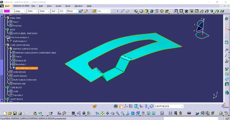
- Using this parting surface we have ti now create the core for the model.
- First, create a new geometry for core design and than insert a sketch with respect to the point and axis which we have created for tooling axis.
- Draw a rectangal as shown in the Image and constrain it.
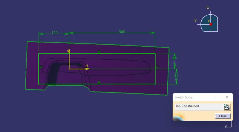
- After the sketch is drawn we have to use the extrude option or tool to and extrude the surface according to the tooling axis direction ( this is very important).
- Now, trim the ectruded surface with the parting surface which we have created before. then close the surface with fill option and join all the surface and make it a close solid body using close surface in part design.
- Finally we will have our core .
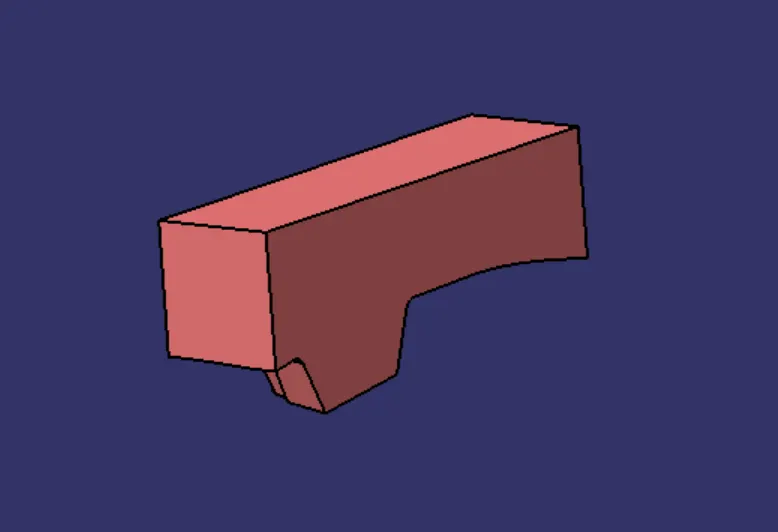
- After the core is created we have to now create Cavity.For that us ethe same sketch which we have created eariler and extrude it along the tooling axis direction.
- After that trim the obtained surface with the class B surface and close the surface with fill tool and make a closed surface with join option.
- After thet use the close surface option in the part design and make is a solid body
- Finally the Cavity is created.
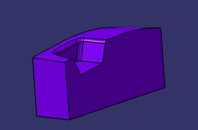
- Finally the cofre and cavity is created.
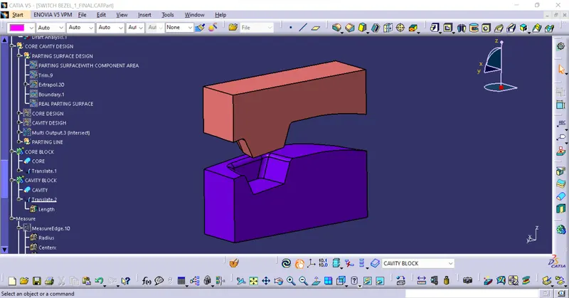
- Now we have to create the parting line.
- To create the Parting line we have to first create joint between the ClassA surface and C surface ,then intersectt the joint with the B surface and we will get the curve and that is our Parting line.

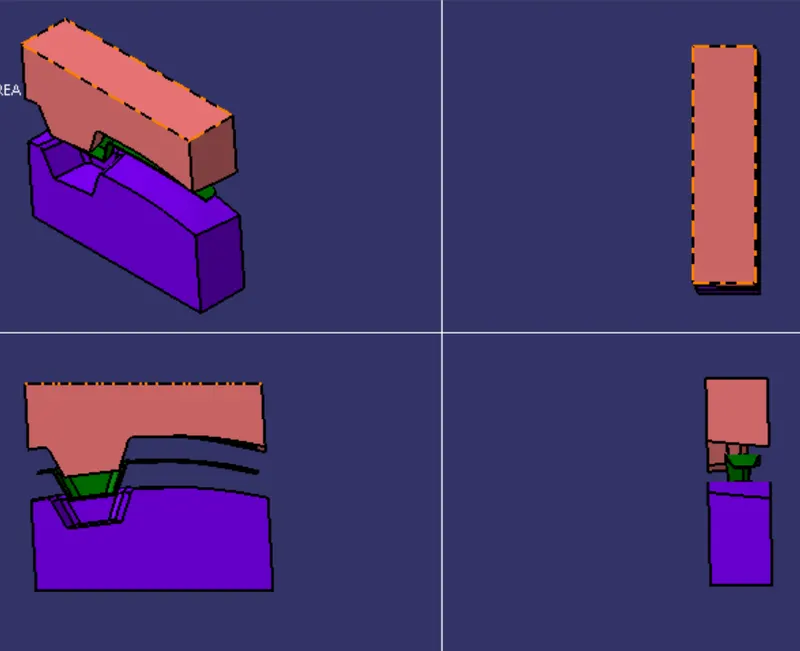
- The Intersection of the whole core cavity will look like as below
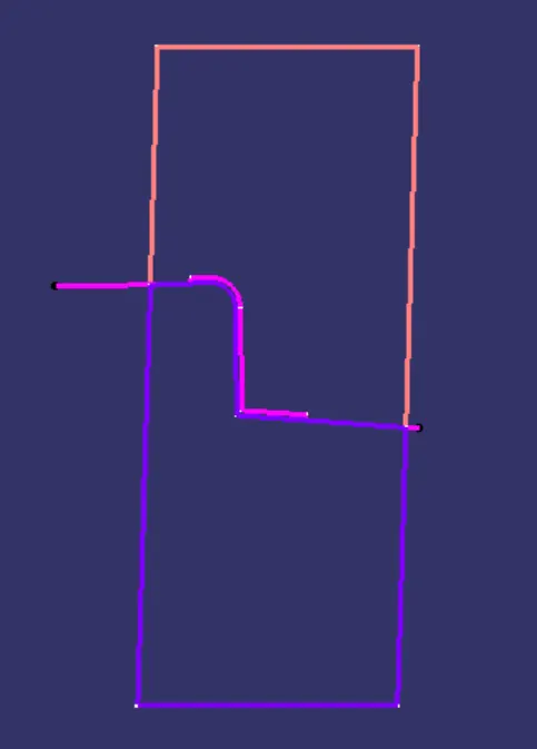
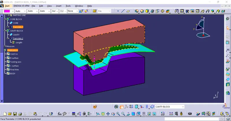
- Apply transition for the core and cavity along the tooling axis to c how the injection molding take place.
WHOLE MODEL:
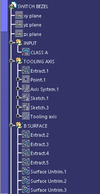
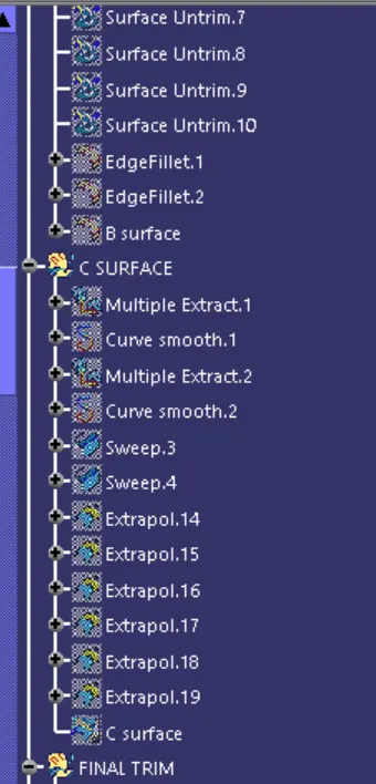
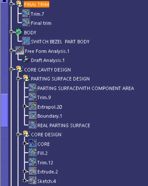
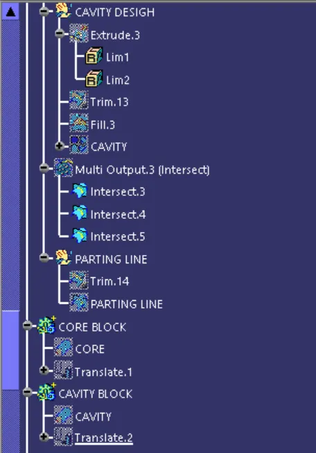
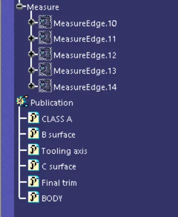
TREE:

VIEWS:
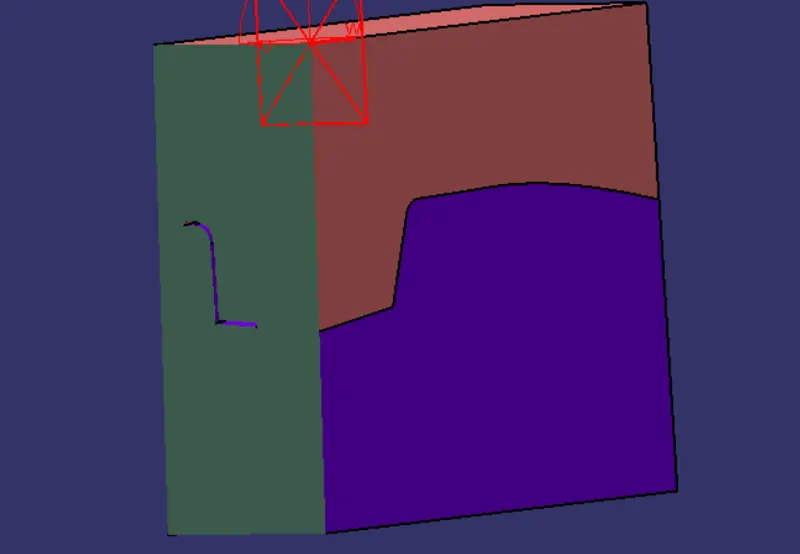
Section view:
CONCLUSION:
Finally, the Core and cavity blocks for the switch bezel are designed.