Week 4- Challenge
1D elements for Parallal bracket with given cross-section and DOF
AIM: To create 1D elements for a given parallel bracket with given cross-section and DOF.
PROCEDURE:
- Import the model by using the import option
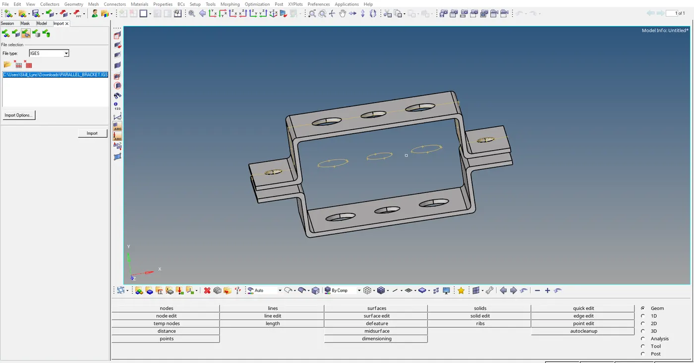
"Image 1: Importing image"
- After importing the model we have to genarate the mid surface for the model.
- To get the midsurface,use midsurface command under the geometry.
- Use automidsurfacing tool to genarate the mid surface.
- select the automidsurfacing in midsurface and than select the model, and finally the mid for the model is generated.
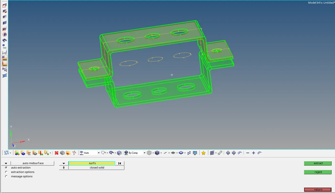
"Image 2: Extracting the midsurface for the model "
- After the mid surface is generated for the model we have to asigne he component Id for the mid surface which is genarated.
- The component id is assigned to mid surface in tab bar. In this model we have assigned 2 component ids ( Bracket 1, Bracket2).
- After the component Id is assigned to the midsurface, delete all the solid surface expect the mid surface.
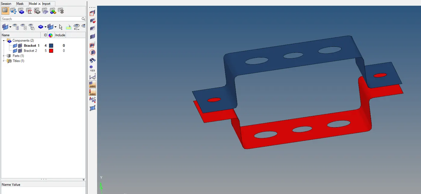
"Image 3: Deleting the extra solid surface "
- Assigne the thickness to the mid surface.
- Now, we have to assigne the meterial,for this model we have assigned the meterial as "steel".
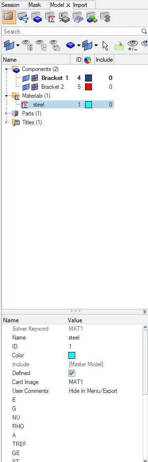
"Image 4: Applying material to the midsurface of the model "
- After the material is assigned, we have to assigne properties to the componets created i.e, Bracket 1 and Bracket 2.
- Assigne the Property for both the components.
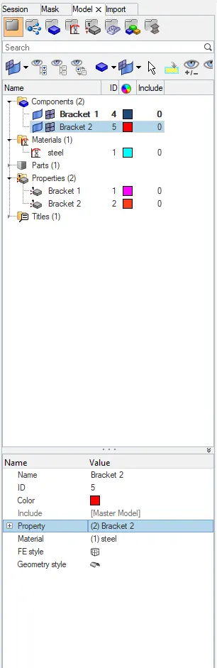
"Image 5: Creating properties for the mid surface "
- Now,create the washer split for the mid surface where ever it is required, to create the washe split, we have to go to quick edit in geometry and select in washer split, select the line and give the offset value ,in the model all the areas (a,b,c,d,e,) requir the washer split.
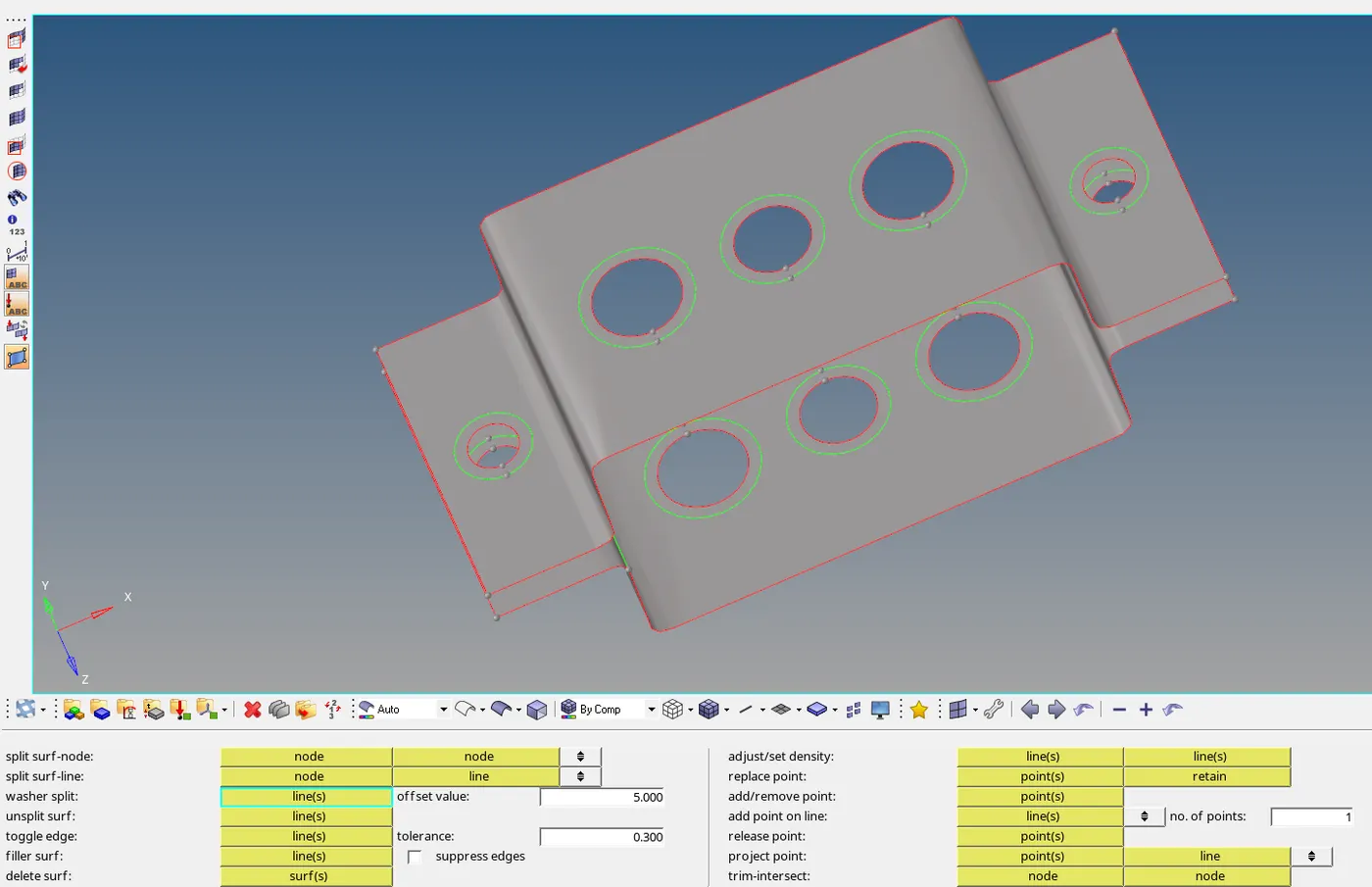
"Image 6: Creating the washer split for the midsurface "
- After the washe split is generated,we have to mesh the midsurface.To mesh the component we have to use the 2D,In 2D select the automesh command.
- Select the whole component which needs to me meshed and then set the element size and execute the command and u will find that the element will be meshed.
- Do some corrections in the mesh near the required parts of the component,
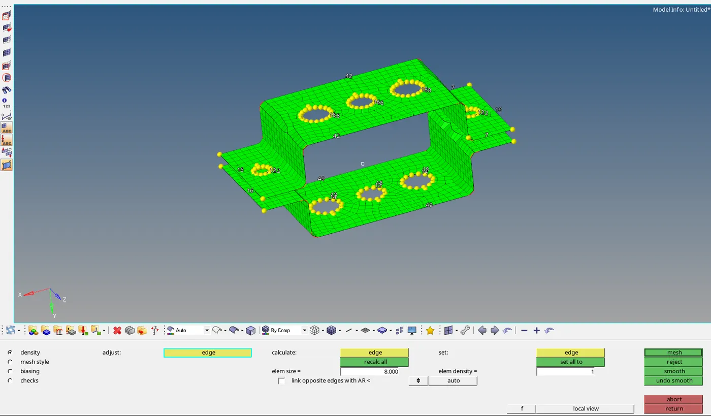
"Image 7: Meshing the midsurface of the model "
- Now hide the original surface from the mesh which is generated.
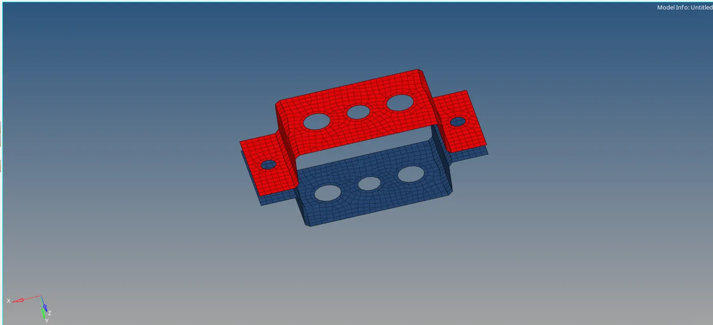
"Image 8: Removing the midsurface after the mesh is generated "
- According to the given model we need to create 1D elements using given information and the give informationis as follows
Given model:
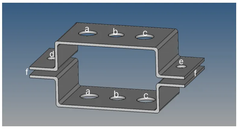
"Image 9: Given model 'parallel bracket "
Given task to execute in the model accordingly:
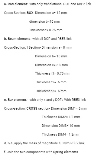
- According to the model, in the region 'a" we need to create Rod element with only translational DOF and RBE2 link, for this first we need to create the RBE2 link.
- To create the RBE2 link, first we have to move to region 'a' and then goto 1D command ,and in 1D command we have to select the rigids option and select multiple nodesaround the region 'a' and then the translational DOF according to the requirement ,and finally when u clikck the create option the RBE2 link is created.
- After the RBE2 link is created in the region A we have to create the rod element in the region,
- As per the given question,the rod element sholud be BOX with the respective dimension and thickness.
- To create a rod element, in 1D tool, select the rods option and select the nodes for RBE2 links, by this CROD element is created. After this to create the box go to HYPERBEAM command in 1D and select standard section.
- In standard section, we have to select the standard section library as HYPERBEAM and standard section type as box. and then a new window will be opened which is called hyper beam window in which we have to give the dimensions and thickness.
- Then we need to assigne the property to the CRODin the tab bar and apply the box which is created in the hyperbeam.
- After applying the box and properties to the CROD and selecting the vector points , we can observe a CROD element with box shape.
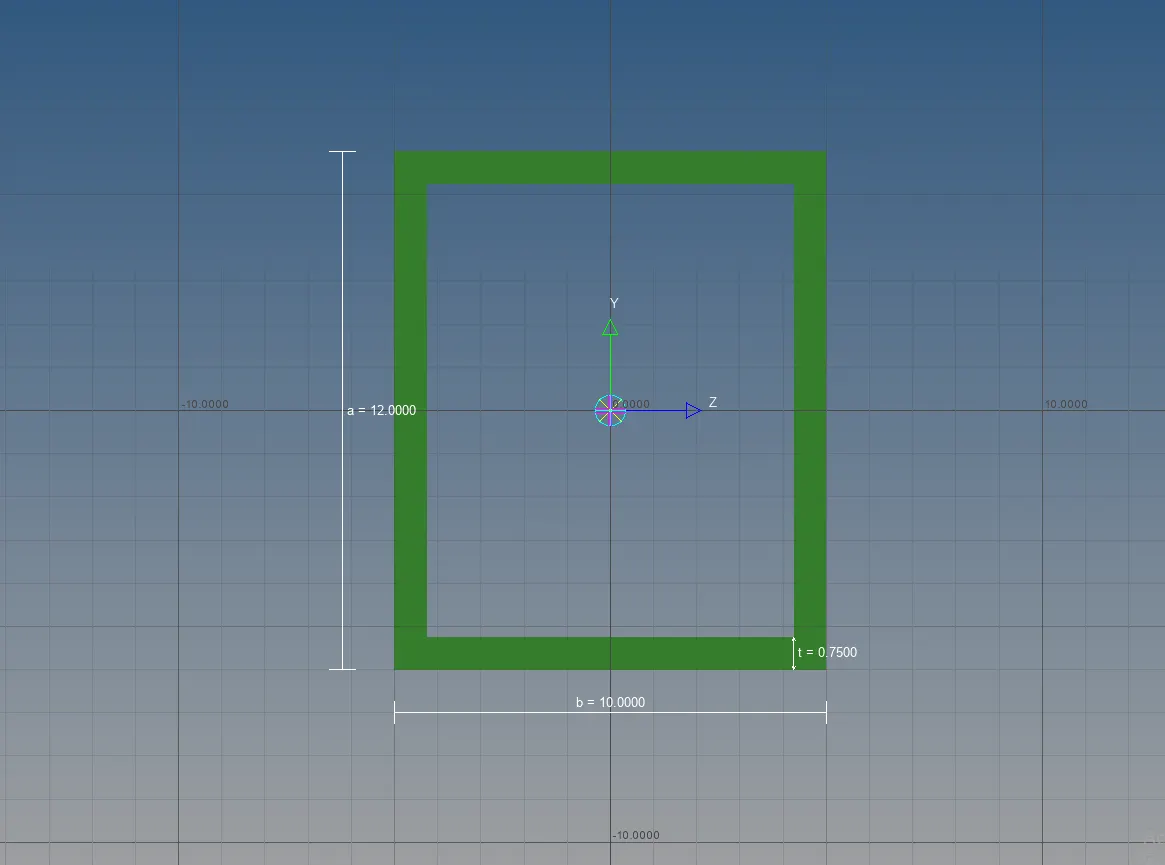
"Image 10: ROD element wih box cross section "
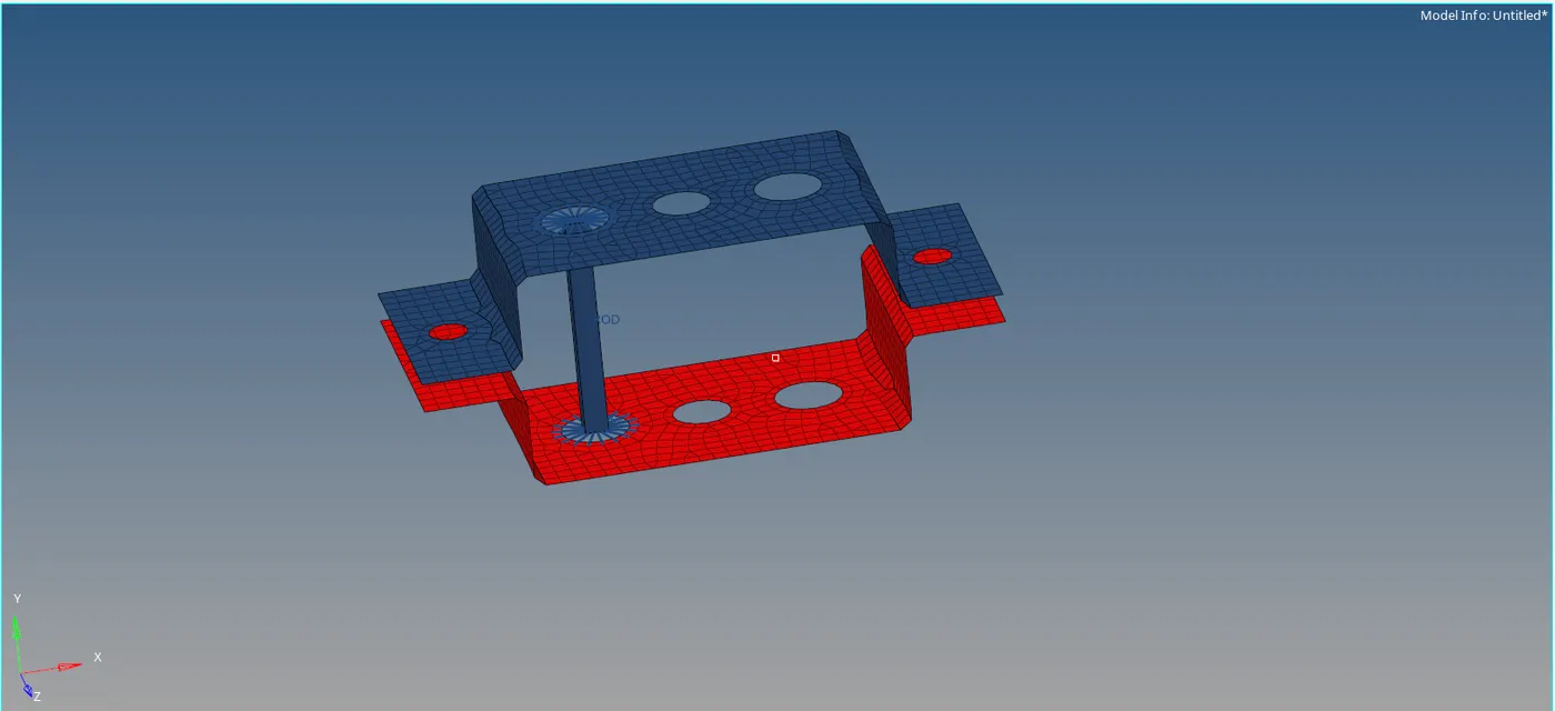
"Image 11: ROD element with box cross section and RBE2 link combined with meshed surface of the model "
- In the came process we can create a Beam element for 'b' region with all DOF and RBE3 links with I-section with given dimenssionsand thickness.
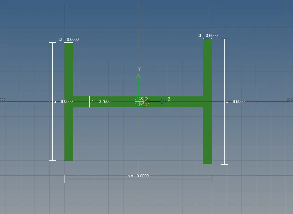
"Image 12: Beam element wih I-cross section "
- in 'c' region for the given we can create a bar element with cross section (T-cross section) according to the given dimensions and thickness
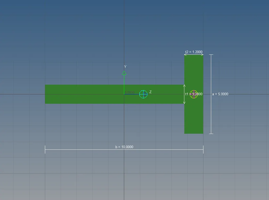
"Image 12: Bar element wih T- cross section "
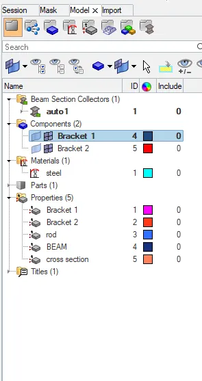
"Image 13: Assigning properties to the ROD,BEAM and BAR elements "
- For the regions 'd' and 'e' in the model, the masses of magnitude 10 with RBE2 link is created by applying MASSES option in 1D command.
- In the 'f' region in the model,the two components are joined with spring elements by using the spring option in the 1D command.
- The thickness is assigned to the mid surface.
- Therefore,the model midsurface is generated,and some 1D elements ared added according to the given questions in respective regions of the model.and the final model looks like
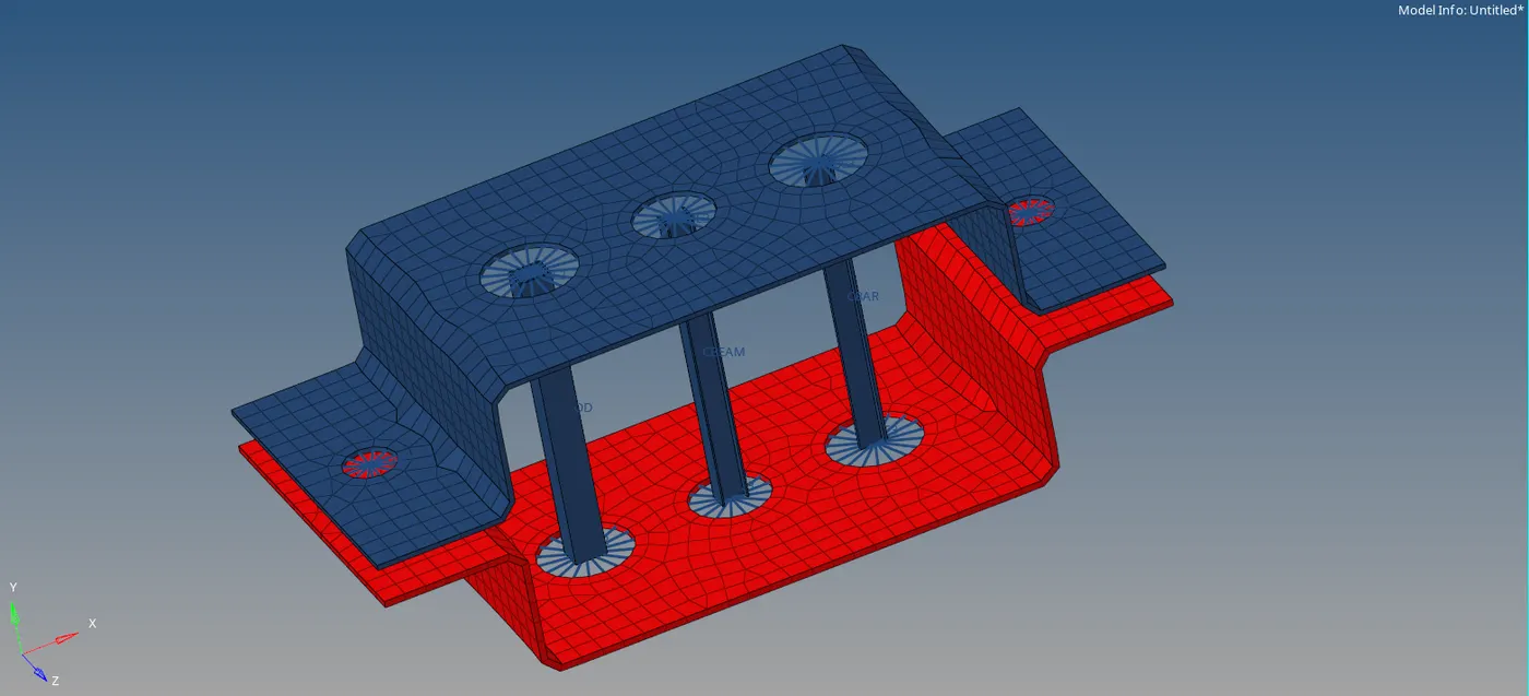
"Image 14: Final model after creating all the 1D elements "
LEARNING OUTCOMES:
- Learned how to extract the mid surface.
- Learned how to assigne thickness for the midsurface.
- Learned how to create a component ID.
- Learned how to assigne a material for a model.
- Learned how to assigne a property for the model.
- Learned how to create a washer split.
- Learned how to mesh the components using automesh.
- Learned howto create RBE2 and RBE3 links.
- Learned how to create rod, beam, bar elements.
- Learned how to obtain hyperbeam by using standard section
- Learned how ro create different standard section types like box, cross sections, I section
- Learned how to assigne the magnitude of masses on the model by using masses in 1D elements.
- Learned how to create spring elements and join to components.
CONCLUSION:
we can conclude that the 1D elements for a given parallel bracket bar created according to the given cross section and DOF respectively.
Google drive link:
https://drive.google.com/file/d/18e80nE5EkPWFKPSnFEo-5YwTf9wckdlG/view?usp=sharing