Week 8 - Challenge 5 - Core & Cavity Design
DESIGN THE CORE AND CAVITY BLOCKS OF SWITCH BEZEL
OBJECTIVE:
The main objective is to design the core and cavity blocks of the switch bezel, and creation of the tooling axis and draft analysis.
PROCEDURE:
TOOLING AXIS CREATION
As the first step we have to check the class-A surface if the proper draft is given or not, so we have to create an axis system to create the tooling axis. For creating an axis system we need a point on the surface, so we have to extract the bottom surface and put the point in the geometrical centre by simply entering 0 in the dimension of the point, this steps are shown below
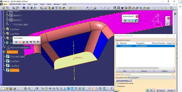
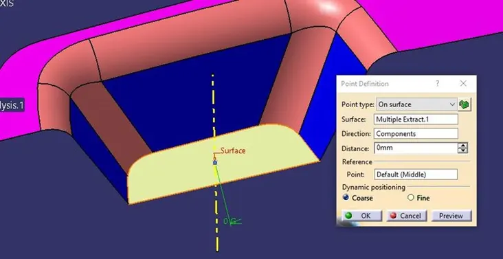
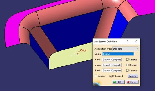
After creating the point we need to place an axis system on that point, we have make sure that we don’t select current option in the axis system.
BISECTING METHOD OF TOOLING AXIS CREATION
In this method the tooling axis is created by bisecting the two lines, this bisecting line needs two lines and a point to create a bisecting line.
Then we have to select plane which intersects the class-A skin and we have to us the intersect 3d elements option to intersect the class-A skin on the plane and make them construction draw two line on the each side of the lines as shown in the picture and now use the bisecting line command and select the two lines to execute the command similarly create the sketch and bisecting line for the other side also in that side we have one face only other face is not present there so we have make a line of our own with a random angle value of 3 degree we can also change the degree if the draft is not achieved, the following images shows the procedure for tooling axis creation.
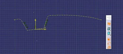
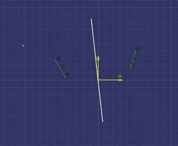
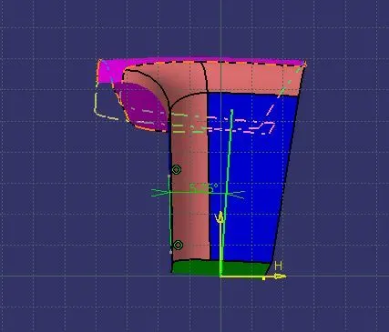
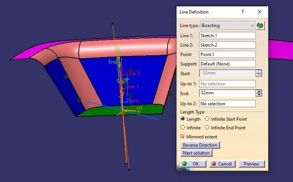
The above picture shows the creation of the bisecting line using the line command in the reference elements, we need to select the two lines we created on the sketch1 and sketch2 and we have select the line command in the reference element then select bisecting line in the line type, then select the line 1 and line 2 after that select the point and choose the proper direction for the bisecting line, now we can name this bisecting line as main tooling axis and also to change the properties to make it visible and publish it for the ease of access.
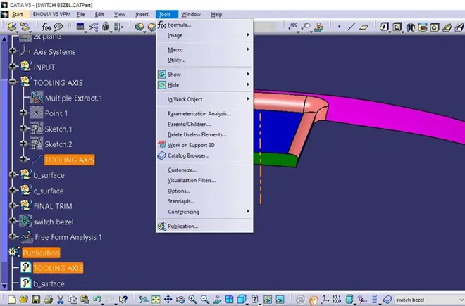
For publication of the tooling axis we have to select and rename the line as tooling axis and after that we have to select the Tools drop down publication menu and select ok in the dialog boxes to create the publication.
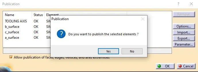
Now we have created the tooling axis, so we can perform the draft analysis. To perform draft analysis we have to put the customize view parameters mode in the view mode and after entering into customize view mode we have to select the material mode as shown in the below image
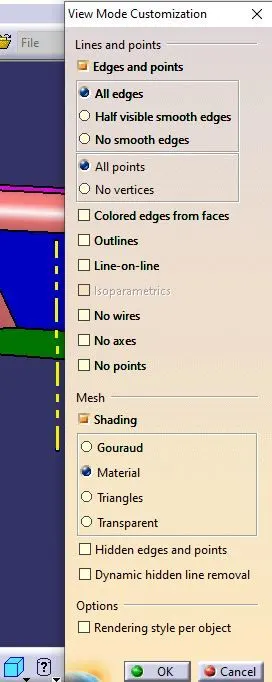
Then perform the draft analysis by selecting the draft analysis icon or by selecting Insert-Analyse-Draft analysis, then we have to select the compass icon on the direction tab of the draft analysis tool bar.
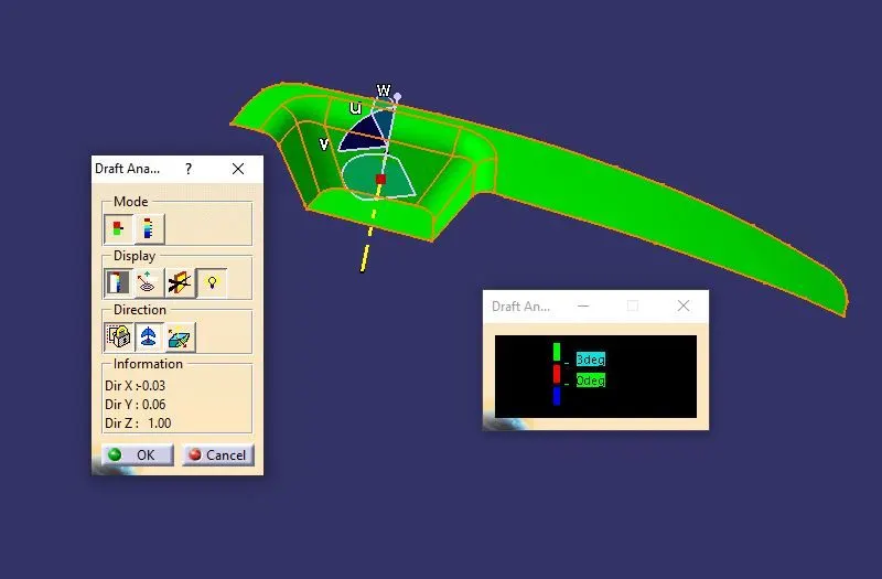
And place the compass on the tooling axis by picking and dragging it on the middle point of the compass, after that press the lock icon on the same tool bar, and click on the any of the surface of the part to perform the draft analysis.
In that small colour code dialog box shows the value of the degree and the maximum and minimum values, this values also can be changed by selecting on the colour codes of the small dialog box, here the draft degrees on that part less than 3 degree will be shown as red colour, and below zero is shown as blue colour, and the values above the 3 degree is shown in green colour and it shows that the part can be manufactured and adequate draft is given.
Then perform the draft analysis for the solid switch bezel part created, then we have to select the compass icon on the direction tab of the draft analysis tool bar.
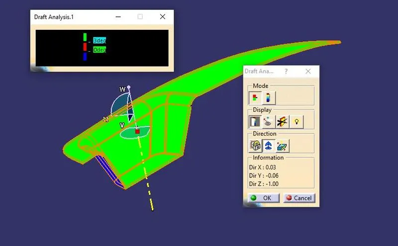
And place the compass on the tooling axis by picking and dragging it on the middle point of the compass, after that press the lock icon on the same tool bar, and click on the any of the surface of the part to perform the draft analysis.
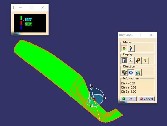
we can also measure the draft angle in the specific area by using the draft under running point icon on the display tab of the draft analysis.
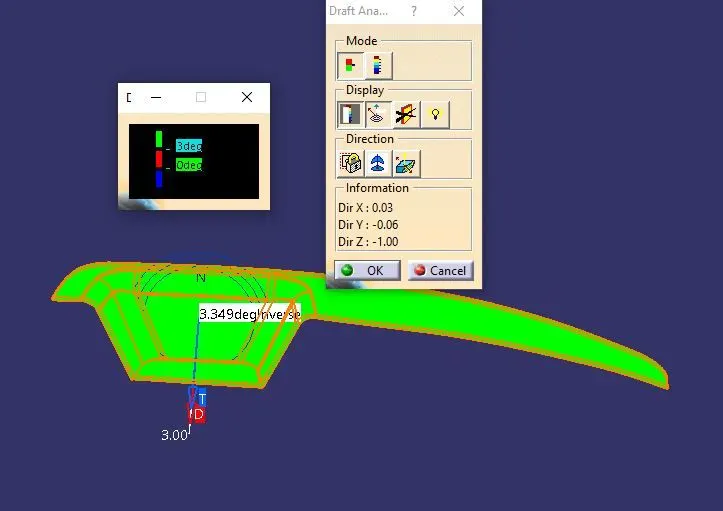
In that small colour code dialog box shows the value of the degree and the maximum and minimum values, this values also can be changed by selecting on the colour codes of the small dialog box, here the draft degrees on that part less than 3 degree will be shown as red colour, and below zero is shown as blue colour, and the values above the 3 degree is shown in green colour and it shows that the part can be manufactured and adequate draft is given.
After performing the draft analysis for both the class-A and the solid part we need to design the core and cavity blocks for the switch bezel part, so insert the geometrical sets for them and maintain the proper tree structure.
CORE AND CAVITY BLOCK
For designing the core and cavity block we need to create the parting surface first then we have to design the core block this also same for the cavity block so we first start with parting surface.
PARTING SURFACE
Parting surface may be defined as the surface in which the two halves of the mold gets pressed against or in other words the parting surface acts as a connection between the core and cavity.
Parting surface directly affects the quality of the product, because the complexity of the parting surface will determine the quality of the mould surfaces, so it is recommended always to have a parting surface which is always less complicated one to achieve it easily while manufacturing the moulds.
Always parting surface should not be designed on the class-A side because most probably some injection moulding defects such as flash or mismatch will happen if we clear that flash with hand tool the corresponding surface will also get affected, so always it is recommended to have the parting surface in the b_surface or non-aesthetic side.
PARTING LINE
Parting line may be defined as the area in which the parting surface and the component meets, it is a junction between the core half, cavity half and the parting surface.
We can get the parting line by intersecting the b_surface with the joined A and C surface to get the parting line, this parting line is the exact junction where the core and cavity opens and closes.
CORE BLOCK
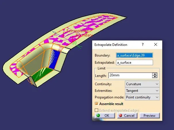
For designing the core block we have to start by extrapolating the class-A surface for enough distance as shown in the below image.
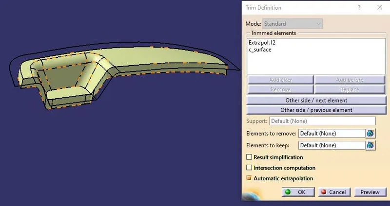
Then check for the c_surface in the feature tree then find it and trim it with the extrapolated A-surface and select the correct direction for trimming.
After trimming the extrapolated A-surface with the C-surface we have to trim the B-surface with it, and choose the correct direction as shown in the below image,
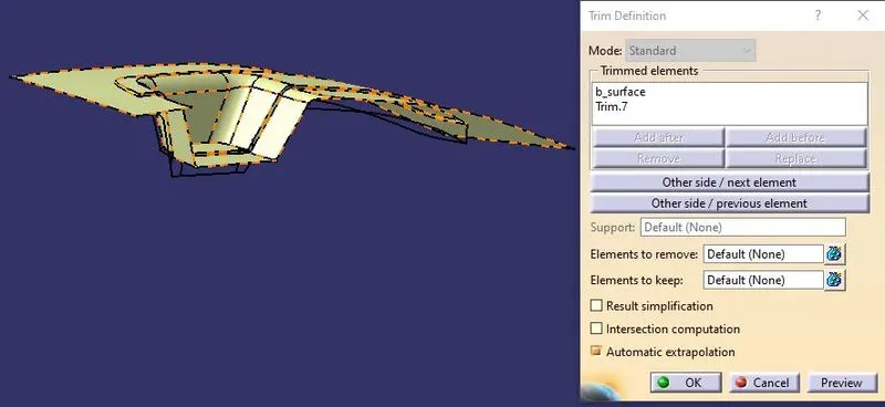
The above surface is the parting surface with component.After creating this trim now we have to design the external shapes of the mould block, we have to draw a rectangle using the axis system and extrude it as a surface and trim the surface with the created parting surface, after that we have to fill the top side and use join command and finally make a solid out of it using the close surface command.
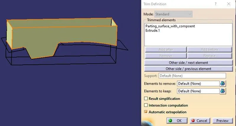
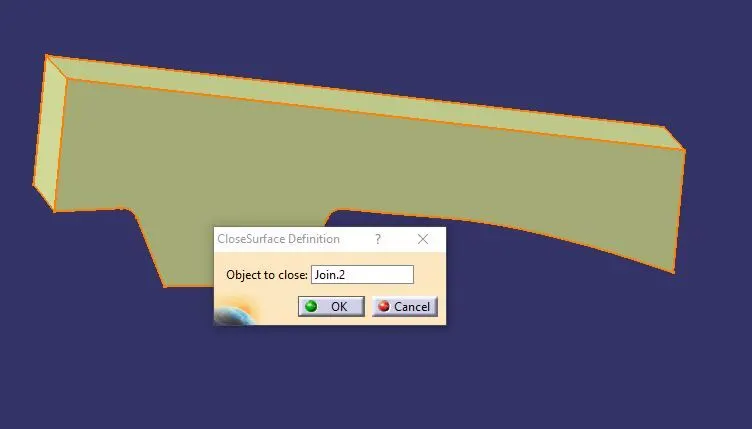
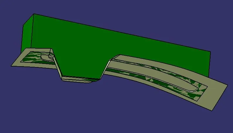
The above complete block is the core side of the mould, after creating solid out of core half we have to publish the core half using the publication option by using the same steps shown above for the class-A surface.
CAVITY BLOCK
Now for creating the cavity block we need to use the extrapolated surface which used for creation of the b_surface, we can find it on the feature tree.
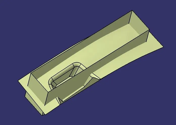
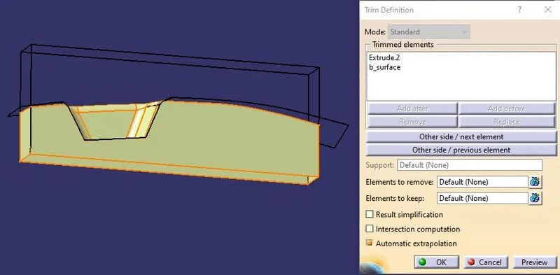
With the use of the sketch we have to create an extruded surface same like the surface for the core side surface, then we have trim that extruded surface with the extrapolated b_surface, after trimming it we can fill the open side of that cavity half and join it and use the close surface command to create the solid out of it.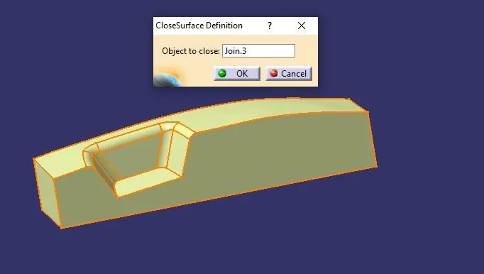
The resulting solid part is the cavity half of the mould, now we have the both core and cavity halves, the parting surface with the component is also shown above and we need to intersect the parting surface with the b_surface to form the parting line and by the use of this parting line we have to split the parting surface with the component area the remaining surface is the actual parting area of the component, it is shown in the below steps
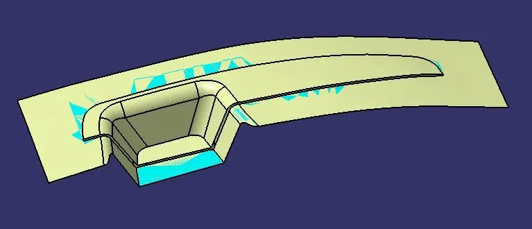
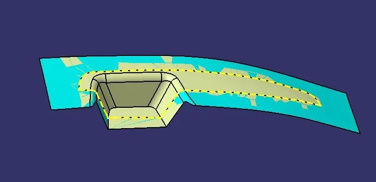
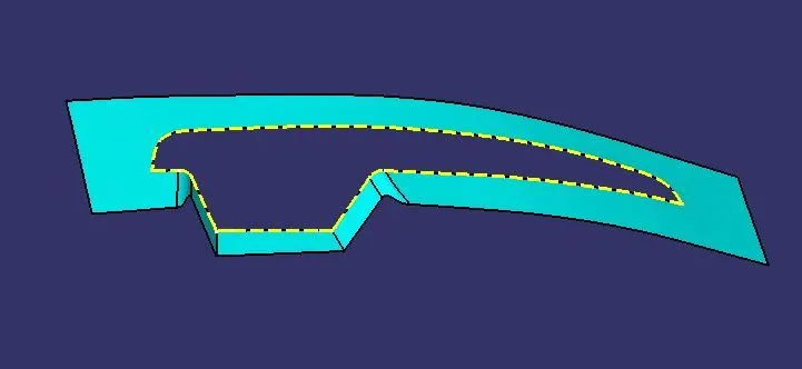
the left side image shows the parting surface with component area and the right side image shows that the parting surface with the component area is splitted by the parting line, and it is the actual parting surface. For better understanding of the design of the mould we can see the section view shown here
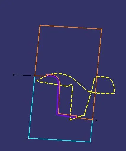
here the orange line highlights the core half of the component, and the cyan colour shows the cavity half of the component, purple colour shows the part and the dashed yellow colour shows the parting line, and black line shows the parting surface.
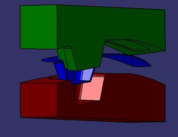
The complete image of the core and cavitya and the plastic switch bezel is also shown below,
CONCLUSION:
Thus the design of the core, cavity blocks for the switch bezel is done and the core and cavity is designed along the tooling direction.