Week 8 - Challenge 5 - Core & Cavity Design
Aim:
Create the Core and cavity blocks for the switch bezel designed in the earlier challenge.
Procedure:
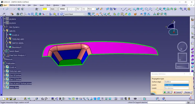
- Check whether the given class A surface is joined and there is no discontinuity.
- Use join or boundary command for this.
Tooling Axis creation:
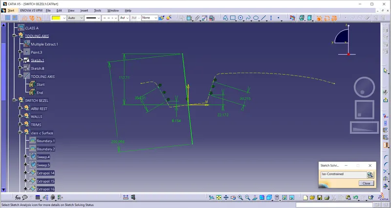
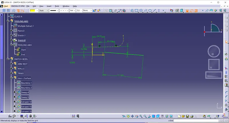
- Creating a sketch on the ZY plane and the Switch Bezel to create a reference tooling axis. (idea is to take reference of two side walls and crating a bisecting line).
- Creating a sketch on the ZX plane and the Switch Bezel to create a reference tooling axis.(idea is to take reference of the centre wall and creating a line of minimum 3 degree to clear in draft analysis.)
- Now a bisecting line is creatine with the help of line option, ehich will be our final Tooling Axis for the switch bezel.
Draft Analysis of the class A surface:
Creation of Class B Surface:
- Extract Bezel Arm Rest Surface,walls and base. Untrim them and extrapolate.
- Offset these features by 2.5mm.
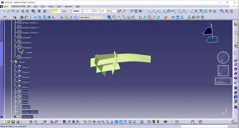
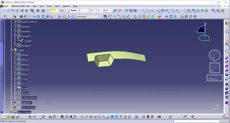
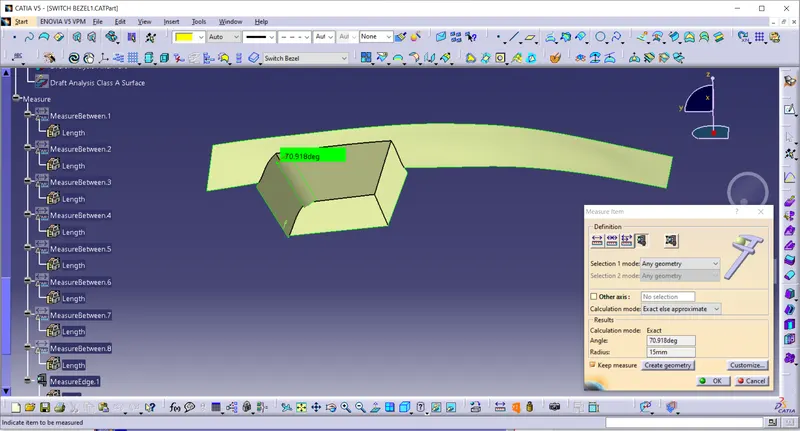
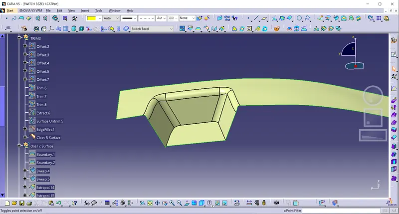
Class C Surface:
- Extract the outside Boundary of the Class A surface to sweep.
- Sweep the Extracted Boundary using Tooling direction as the draft direction and give 3mm as Draft angle.
- Join Class A and Class C surface.
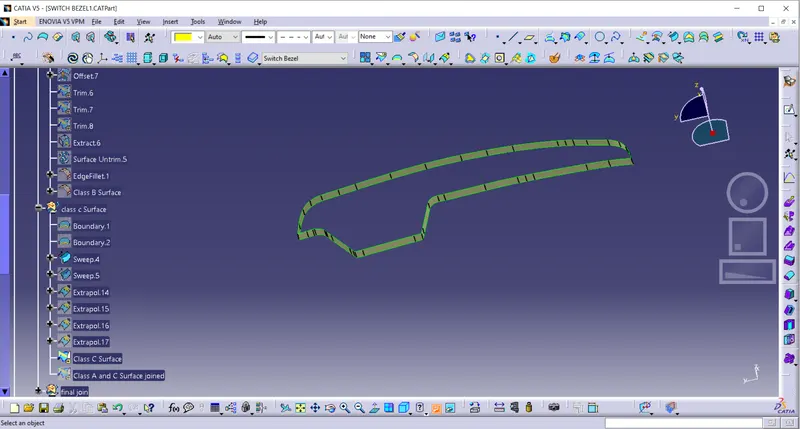
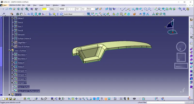
Trim the Joined surface with Class B surface to get the final model.
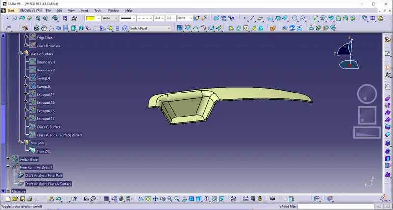
Now Define Part Workbench and use Close Surface tool to produce a solid body from the above surface created.
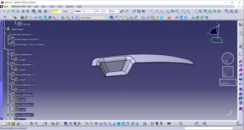
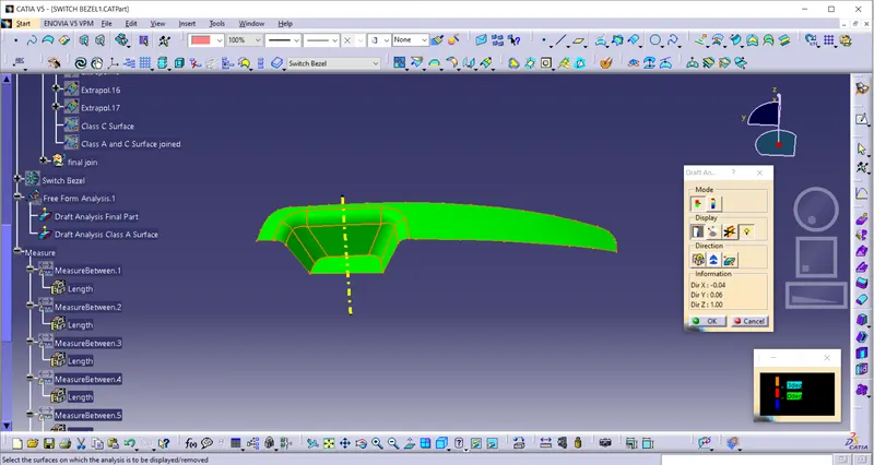
Now perform the draft analysis on this final solid model.
- Insert->Analysis->Draft Analysis
- Drag the Compass and align it with the Tooling axis
- Click on the Solid body and it will be differentiated with colors according to the Draft angle of the body with the tooling axis. If the colour is Green, the draft angle is more than 2.9 degrees and it will clear the tooling axis, if colour is Red, the draft angle is more than 0 degrees and less than 2.9 degrees, if colour is Blue, draft angle is less than 0 degrees and it won’t clear tooling axis and draft angle must be changed.
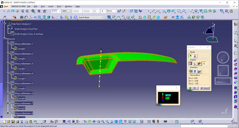
CORE & CAVITY DESIGN:
PARTING SURFACE:
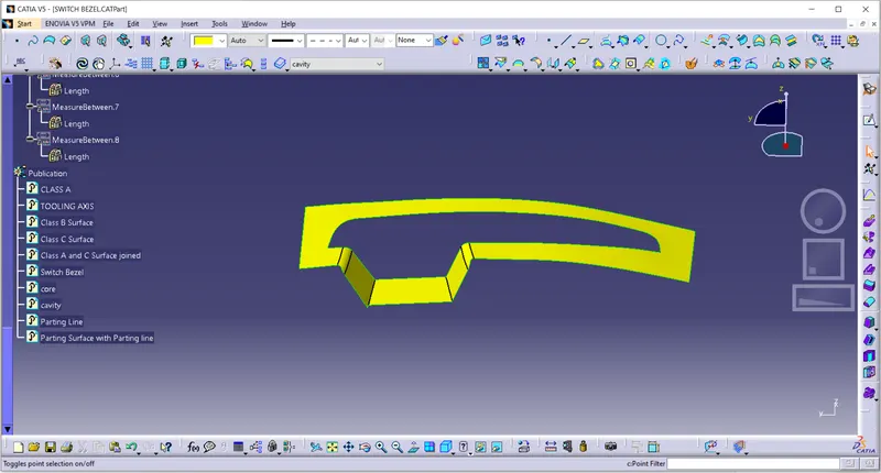
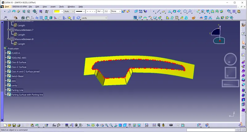
PARTING SURFACE along with PARTING LINE:
CORE:
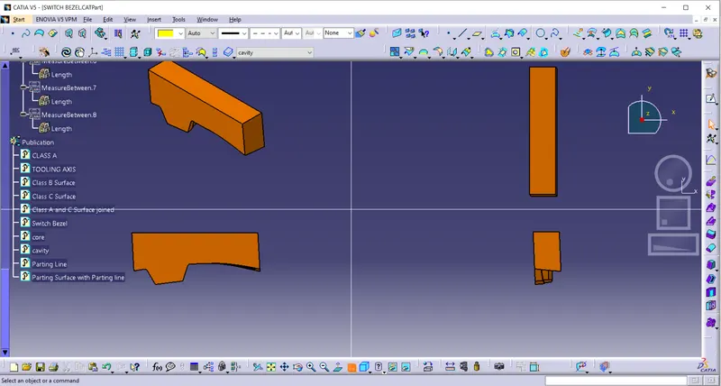
CAVITY:
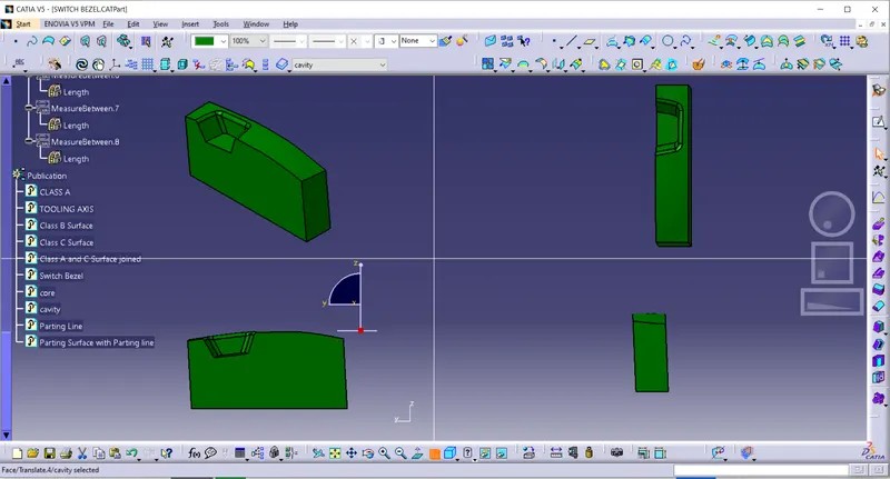
Final output:
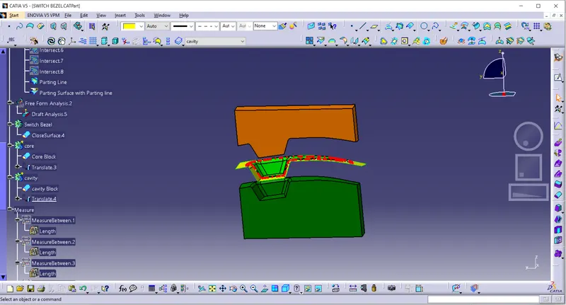
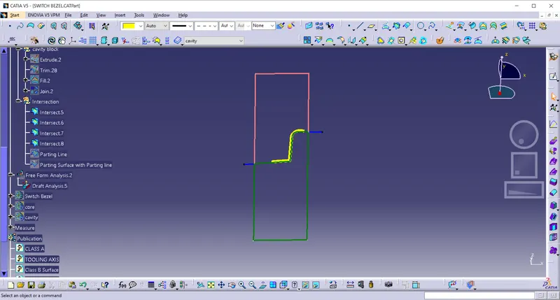
Tree structure and Publications:
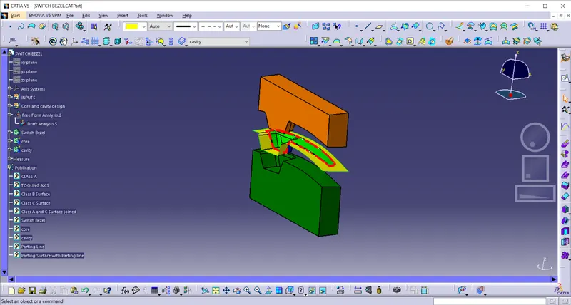
CONCLUSION
- Tooling axis is created and Draft Analysis is done on Class A surface.
- Class B and Class C surfaces are developed and a Close surface is created.
- Draft analysis is done on Switch Bezel with a nominal draft angle of 2.9 degrees.
- Parting Surface is created.
- Core and Cavity parts are created.