Week 8 - Challenge 5 - Core & Cavity Design
AIM: To create the core and cavity blocks for the switch bezel which we have designed in the earlier challenge.
THEORY:
DRAFT ANALYSIS:
The Draft analysis command enables you to detect if the part you drafted will be easily removed. This type of analysis is performed based on color ranges identifying zones on the analyzed element where the deviation from the draft direction at any point, corresponds to specified values.
PARTING SURFACE:
Generally, injection mold has two major components, the movable halve and the fixed halve, during the injection molding process, these two halves are pressed tightly from a sealed hollow to avoid the melt flow leakage and maintain certain holding pressure, the pressed surface are called parting surface, usually parting surface are the biggest projection outline of the part.
Parting surface design principles:
Parting surface design directly affects the product quality, ease of construction and operation of the injection mold, the mold design is one of the key factors to success.
Principles to follow to design parting surface:
- Design the injection mold simple as possible. Avoid or reduce side parting as much as possible to reduce complexity of the mold making.
- Ease of de-molding as far as possible, for instance the plastic parts should stay in fixed halve of injection mold and should ejected by ejection system avoid, side de-molding action.
- Ensure the dimension accuracy of the molded parts; try to make the parts similar dimension accuracy requirements in same mold to reduce manufacturing and assembly errors.
- Ensure appearance requirement of molded parts, finish or mismatch usually occurs on parting surface, so the parting surface should not be designed on high quality requirement surfaces.
- Ensure adequate venting. If possible parting surface should be placed at the end of the mold flow. This is going to be advantage of filling and venting.
PARTING LINE:
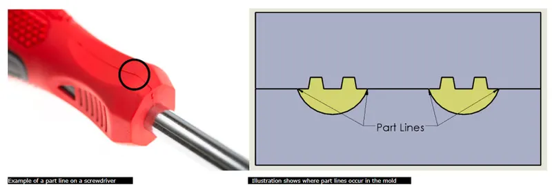
Part lines are where the two halves of the mold meet. This generally creates a physical line on a part that is both visible and noticeable to the touch. These lines, however, can be hidden or minimized when placed along edged of the part, when designing a part, always keep in mind its part lines.
DESIGN RULES OF CREATING CORE AND CAVITY:
To create a plastic part there are two major components core and cavity. The core has the impression and the cavities have the depression.
Design rules-:
- The proper draft should be given to the part so that the part can be ejected from the core and cavity.
- Minimum 3 degree draft should be given to the class C surface. If the part has 0 degree draft then there will be friction occurs in the core and cavity.
- The side core should be avoided because the manufacturing cost of the component increases.
- The parting line is the line that split the mold into two halves the core and the cavity. So the parting line should be always in the class B surface so that we cannot see the parting line.
- Avoid sharp corners ass the cost to manufacture the sharp corner is very high.
- The thickness of the part should always have uniform thickness throughout the part.
PROCEDURE:
When you look at the part we have designed the color highlighted region side is the core side since it have the projections. Here we are extrapolating the class A so that we can use it for trimming purpose while creating core and cavity blocks.
If we can observe from draft analysis we have done on this component in the previous challenge the A surface and C surface had tooled along A side i.e., “Main tooling axis” direction.
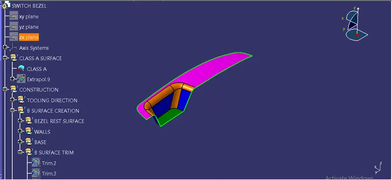
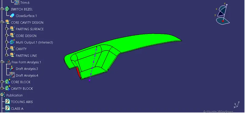
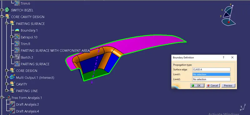
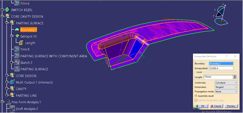
So we are considering it as a part of core. For creating core we need untrimmed class C and class B surface which we created before. Here we are trimming class B with extrapolated class B.
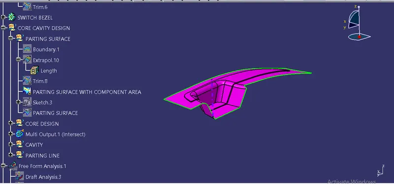
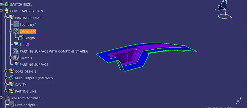
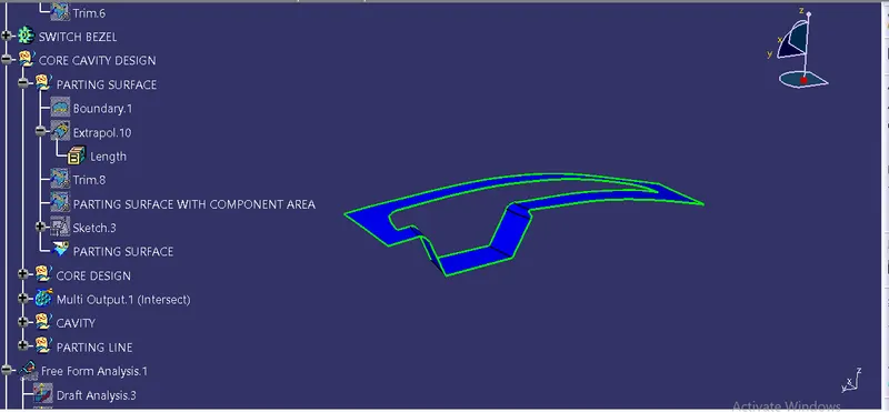
We have slitting surface between core and cavity i.e., parting surface which defines where the core and cavity is going to split and features which comes after it.
Now we are creating a rectangular shape sketch so that it can cut off the surface.
While creating we can also make sure that the boundary of the sketch is inside the parting surface.
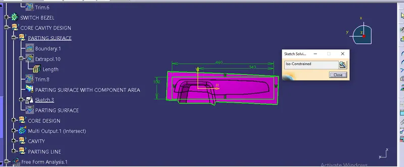
After iso-constraining the sketch we named it as parting surface. Then we will extrude it along tooling axis in separate geometrical set naming “core design”,
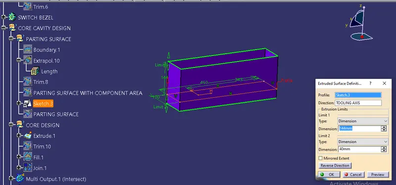
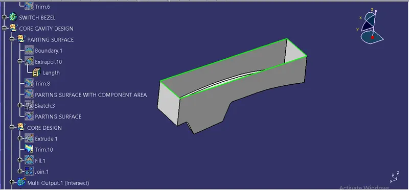
Later we trim the core along with the parting surface and extrude surface. The image below shows how a core looks like.
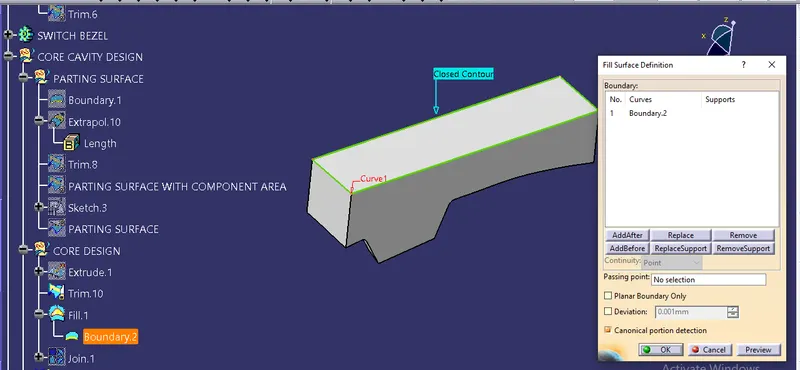
And we will extract the boundary and fill the top to make it closed surface so that we will get the core solid block out of it.
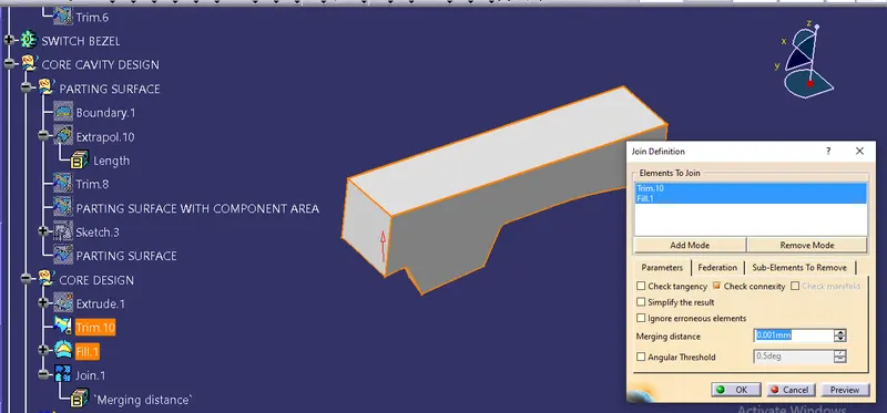
- Use the Close surface feature to make a solid body from the surface.
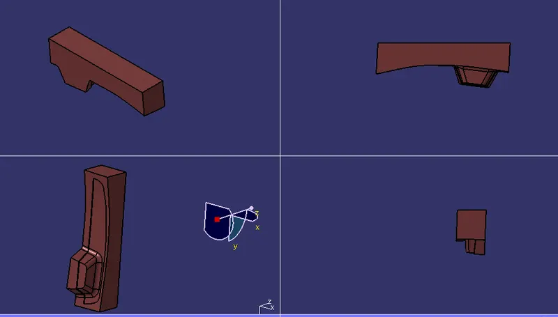
Here we will use intersection between x plane with parting surface and core. The pink color shows the core, yellow is the core where its walls are extruded alum and the blue shows the parting surface which split the core and cavity, always ensure to have parting surface on B side.
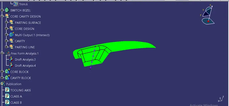
Now let’s design the cavity, we follow the same process as above first we will extrude the surfaces/walls along tooling axis direction, we ignore the component area and trim the body with B surface and then fill the bottom portion to make it closed body for solid block/cavity block.
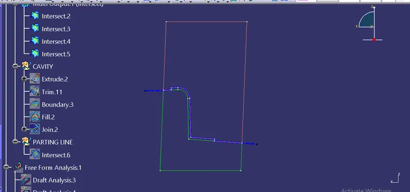
Here after making cavity block we made the intersection with the X-axis again. The image below shows the cavity block which is in green and the blue dotted highlighted is the parting surface.
Generally, injection mold has two major components, the movable halve and the fixed halve, during the injection molding process, these two halves are pressed tightly from a sealed hollow to avoid the melt flow leakage and maintain certain holding pressure, the pressed surface are called parting surface, usually parting surface are the biggest projection outline of the part.
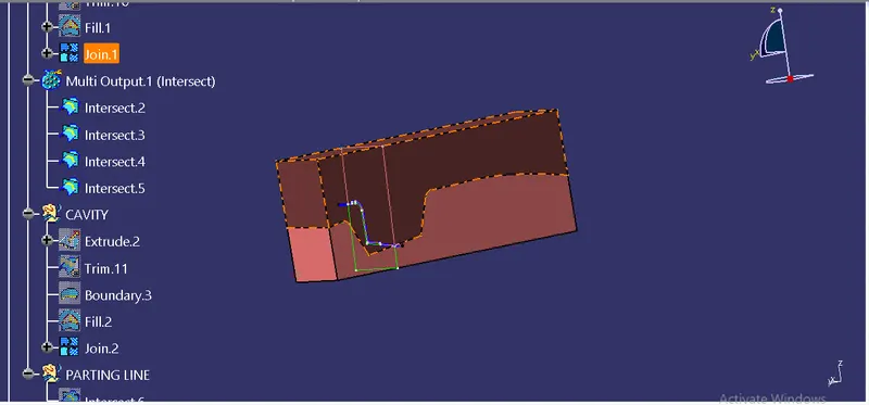
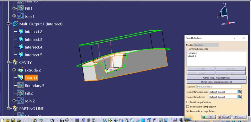
- Use the Close surface feature to make a solid body from the surface.
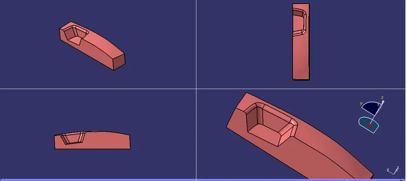
Parting line is the area in which parting surface and component meets or core half and cavity half meets/junction between the parting surface and the component.
Here we will intersect A and C surface joined together with B surface so that we will get parting line which is clear splitting line between core and cavity. It is very exact junction where core and cavity closes at the parting surface and intersection of the component with parting surface is the parting line.
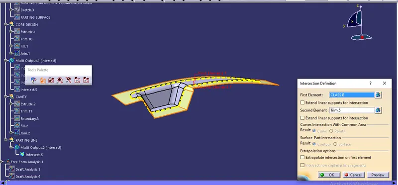
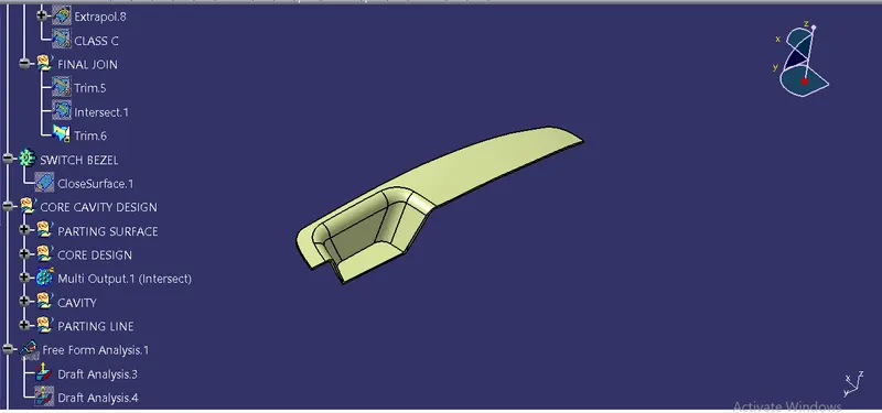
We have created the parting surface to make sure it is easy for creating core and cavity block but parting surface is actually whatever is outside the component area. So split the parting surface with the parting line which gets us the actual parting surface.
The yellow surface image below shows the actual parting surface.

Finally we will be translating the parts separately for easy understanding between core, cavity, component, parting line and surface.
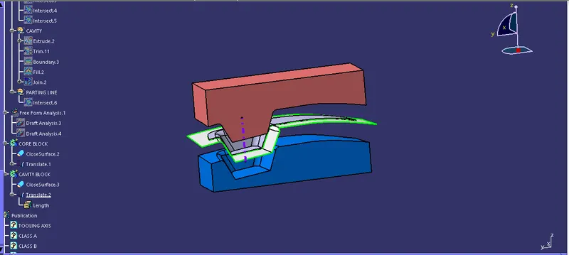
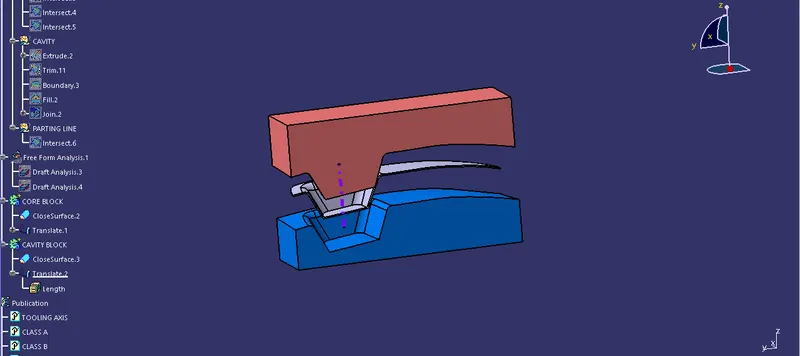
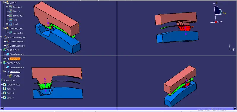
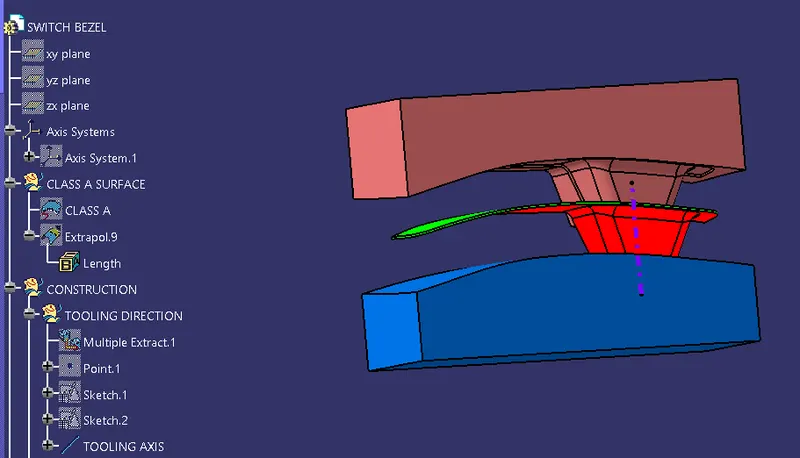
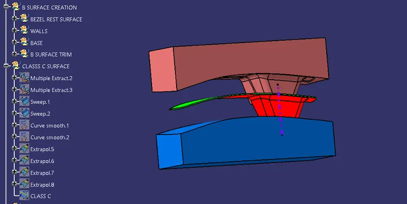
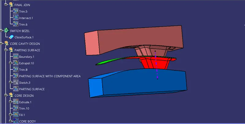
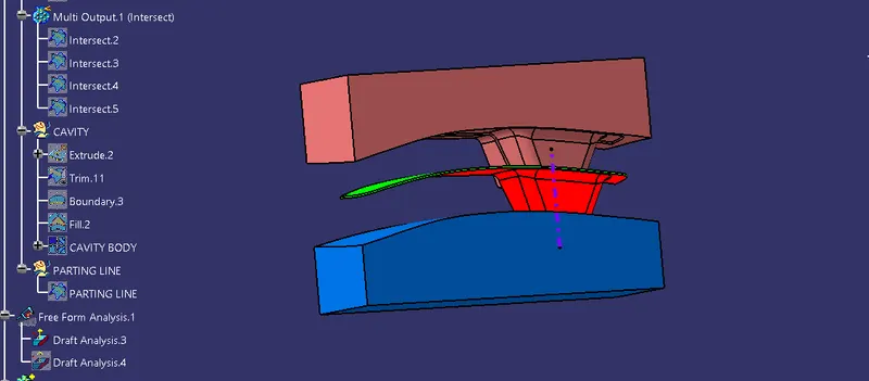
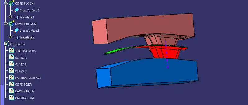
- Publications: Use the publication option and published as show below.
- Tooling axis
- Switch Bezel solid / Surface body
- Parting line and parting surface
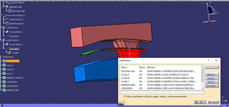
RESULT: Finally we have created the core and cavity blocks for the switch bezel that we designed in the last challenge.