Photo Realistic Rendering
AMERICAN CHOPPER
Objective:
The objective of this project is to understand and demonstrate the design philosophy of a American
chopper motorcycle model using new age design tool --- Solid works. In the design, assembly and the
rendering phases, usage of sketch tools and making sure that it is fully defined, importance of mates in
assembly, usage of rendering tools in photo view 360 as well as Solid works Visualize is completely dealt with
understood.
Introduction:
Solid works:
Solid works is a solid modelling computer-aided design (CAD) and computer-aided engineering (CAE) program
published by Dassault Systems.
Solid works has three basic environments namely: Part, Assembly and Drawing.
In part modelling we will be using parameters include numerical values such as lengths, diameter/radius as
well as geometrical components like tangency, collinearity, parallel, concentricity, vertical, horizontal etc.
Converting 2d sketches into 3D models require feature-based approach. some of features are extrude boss,
extrude cut, revolve, revolve cut, shell, loft, sweep, hole, fillet, chamfer, slot etc.
Assembly, in this environment the mates determine the final assembly and relation of various parts to each
other.
Drawing, environment is mainly used to create 2D sheets with all main views of the solid parts and assembly.
File formats in Solid works:
Parts: (. SLDPRT)
Assembly: (. SLDASM)
Drawing: (. SLDDRW).
Solid works also has products such as photo view 360 for appearance, scenes and photorealistic renderings
inside Solid works environment.
To accomplish the objective of the project and successfully model the American Chopper, following parts are
to be modelled.
• Transmission Belt
• Kick Stand
• Front Fender
• Rear Fender
• Chain
• Oil Tank
• Pedal
• Front Wheel
• Rear Wheel
• Front Fork
• Chassis
• Engine
• Gas Tank
Design methodology:
3D
modelling of
parts
Applying
materials
and decals
to individual
parts
Assembly Final Render
Final Render
Add and
adjusting camera
Add and
adjusting
Lighting
Add and adjust
Background
Add and adjust
Scenary
Description:
Solid modelling of all the parts of the American Chopper Motorcycle.
1.Transmission Belt: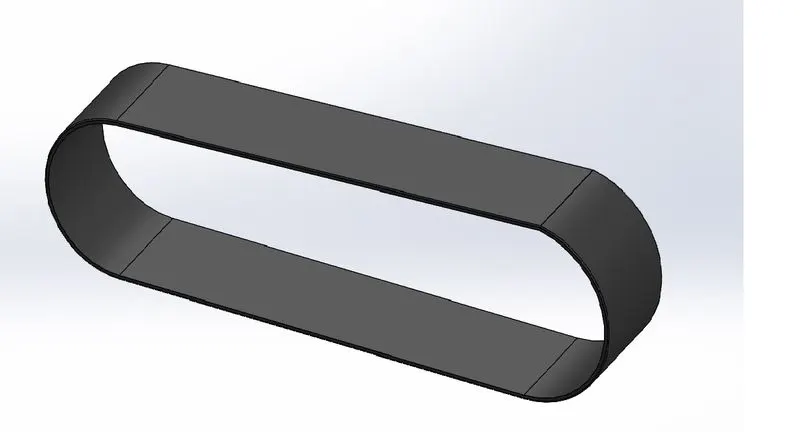
Tools used:
Sketch tools:
• 3 Point arc
• Line
• Sketch offset
Features:
• Extrude
• Fillet
• Appearance
2.Kick Stand: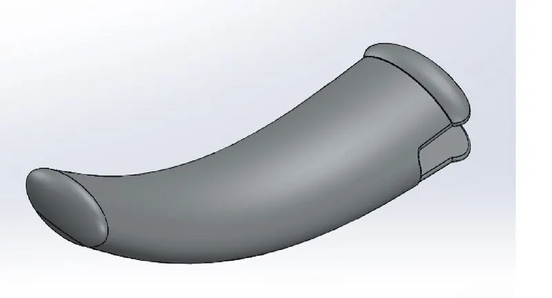
Tools used:
Sketch tools:
• Ellipse
• Spline
• Pierce
Features:
• Loft
• Split
• Dome
• Extrude Boss
• Extrude Cut
• Fillet
• Appearance
3.Front Fender:
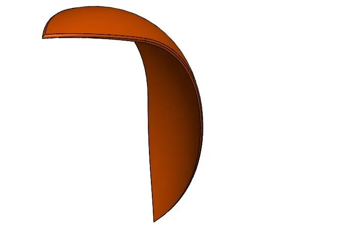
Tools used:
Sketch tools:
• 3 Point arc
• Sketch offset
• Line
• Spline
Features:
• Revolve
• Split
• Dynamic mirror entity
• Fillet
• Appearance
4.Rear Fender:
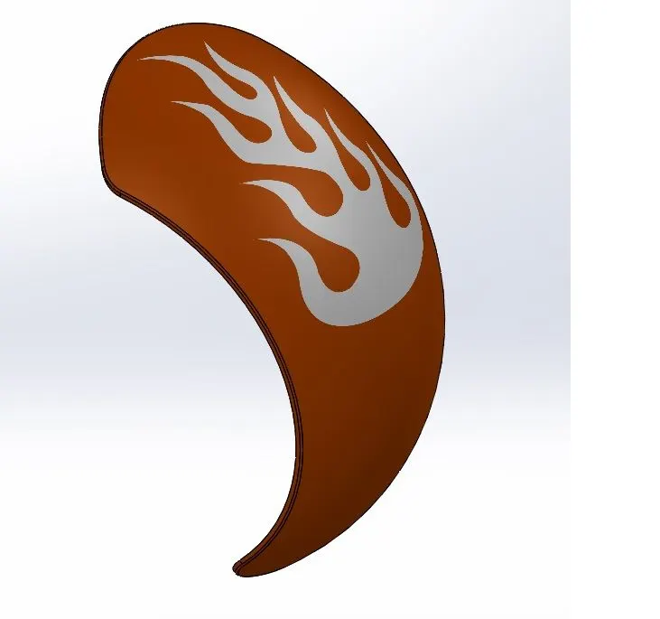
Tools used:
Sketch tools:
• 3 Point arc
• Sketch offset
• Line
• Spline
Features:
• Revolve
• Split
• Shell
• Dynamic mirror entity
• Fillet
• Appearance
5.Chain:
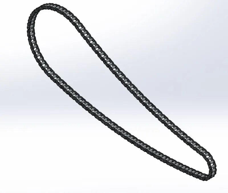
Tools used:
Sketch tools:
• 3 Point arc
• Centrepoint slots
• Circle
Features:
• Extrude boss
• Make and save block
• Fillet
• Curve driven pattern- tangent to curve
• Mirror
• Appearance
6.Oil Tank:
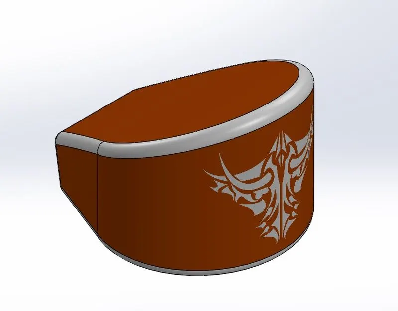
Tools used:
Sketch tools:
• 3 Point arc
• Line
Features:
• Extrude boss/base
• Fillet
• Combine
• Shell
• Appearance
7. Pedal:
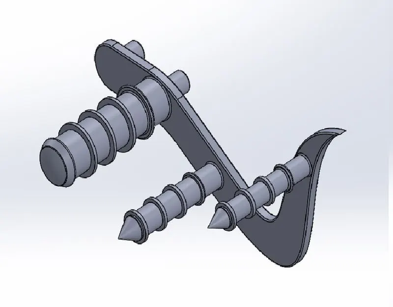
Tools used:
Sketch tools:
• 3 Point arc
• Circle
• Spline
• Line
• Sketch fillet
Features:
• Extrude boss
• Revolve
• Fillet
• Dome
• Chamfer
• Linear pattern
• Appearance
8. Front Wheel:
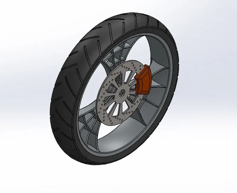
Tools used:
Sketch tools:
• 3 Point arc
• Lines
• Splines
• Mid-point line
• Circle
• Sketch fillet
• Trim
• Extend
• 3-point centre rectangles
Features:
• Revolve boss/base
• Extrude boss/base
• Extrude cut
• Revolve cut
• Circular pattern
• Combine
• Fillet
• Chamfer
• Appearance
9. Rear Wheel:
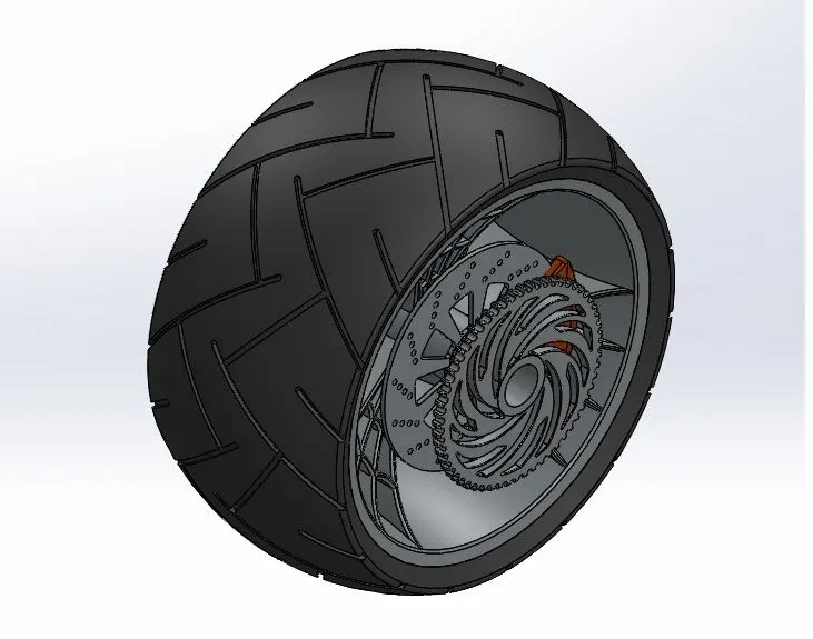
Tools used:
Sketch tools:
• 3-Point arc
• Lines
• Splines
• Mid-point line
• Circle
• Sketch fillet
• Trim
• Extend
• 3-point center rectangles
Features:
• Revovle boss/base
• Extrude boss/base
• Extrude cut
• Revolve cut
• Circular pattern
• Combine
• Fillet
• Chamfer
• Appearance
10. Front Forks:
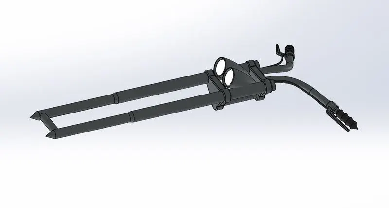
Tools used:
Sketch tools:
• 3-Point arc
• Lines
• Splines
• Circle
• Trim
Features:
• Revolve boss/base
• Extrude boss/base
• Linear pattern
• Extrude cut
• Revolve cut
• Dome
• Body move/copy
• Curves-Projected
• Sweep
• Reference geometry- planes
• Mirror
• Combine
• Fillet
• Chamfer
• Appearance
11. Chassis:
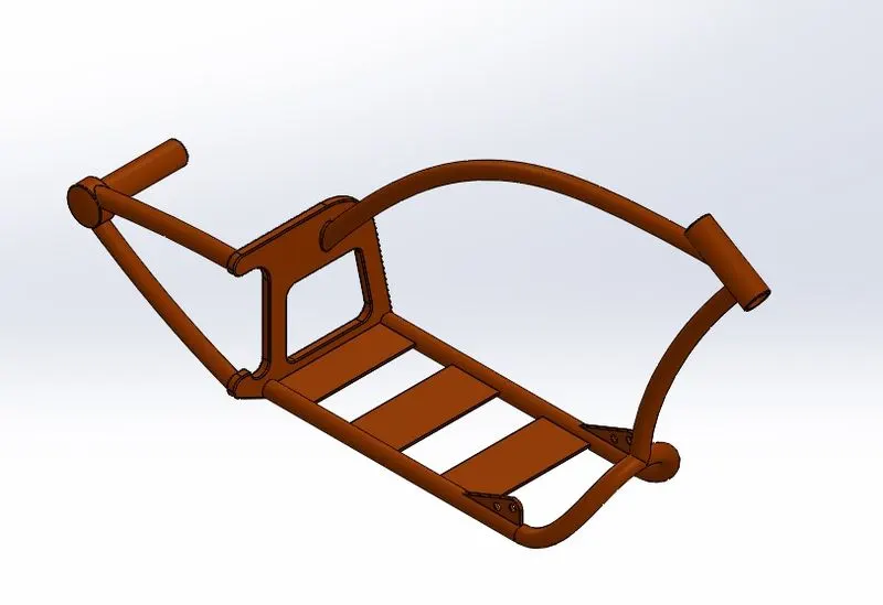
Tools used:
Sketch tools:
• Sketch Picture
• Lines
• Splines
• Circle
• Trim
Features:
• Extrude boss/base
• Extrude cut
• Revolve
• Dome
• Curves-Projected
• Sweep
• Split
• Reference geometry- planes
• Mirror
• Combine
• Fillet
• Chamfer
• Appearance
12. Engine:
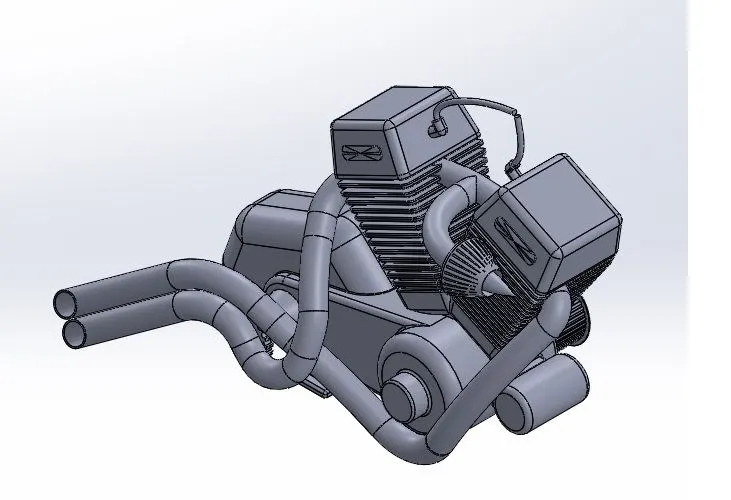
Tools used:
Sketch tools:
• Sketch Picture
• Lines
• Splines
• Circle
• Circular sketch pattern
• Construction line
• Centre point rectangle
• 3-point center rectangle
• Trim
Features:
• Extrude boss/base
• Extrude cut
• Revolve
• Dome
• Curves-Projected
• Sweep
• Split
• Reference geometry- planes
• Circular pattern
• Linear pattern
• Mirror
• Combine
• Fillet
• Chamfer
• Appearance
13. Gas Tank:
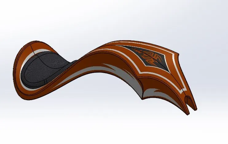
Tools used:
Sketch tools:
• Sketch Picture
• Lines
• Splines
• Construction line
• Trim
Features:
• Surface sweep
• Surface loft
• Surface trim
• Boundary surface
• Surface knit
• Surface Extrude
• Curves
• Projected curves
• Split line
• Sweep cut
• Reference geometry- planes
• Mirror
• Shell
• Fillet
• Appearance
14.Assembly:
American Chopper Motorcycle Assembly:
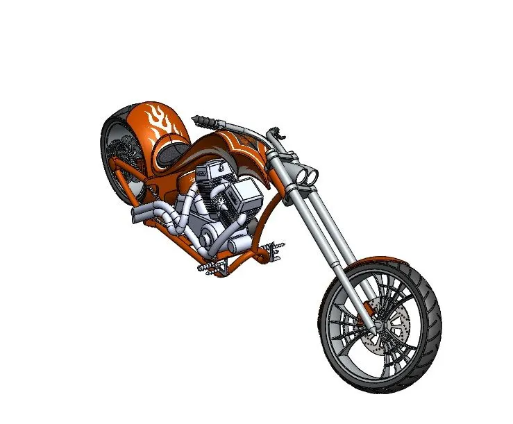
Mates in assembly:
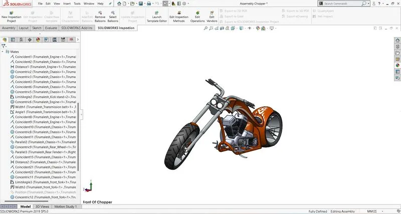
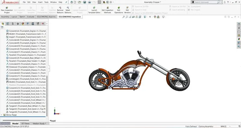
Mates in assembly environment is analogous to relations in part environment.
Basically, it is the relation between two different components. Solid works assembly mates
consists of 3 main mates namely Standard mates, Advanced mates and Mechanical mates.
Standard mates consist of: Coincident, Concentric, Parallel, Perpendicular, Tangent, Lock,
Mate alignment angles and distance mates.
Advanced mates consist of profile centre, Symmetric, Path mate, Width mate, Linear/Linear
coupler, Angle and distance mates.
Mechanical mates consist of Cam, Slot, Hinge, Gear, Rack & Pinion, Screw, Universal joint.
• Photorealistic Rendering
Rendering of the assembly is done to make a good quality 2D images for the purpose
of advertising and promotion of the products before selling it to the customers.
Photorealistic rendering creates high quality images or motion graphics if available
so as to look appealing in various environments and back drops.
• Photoview 360:
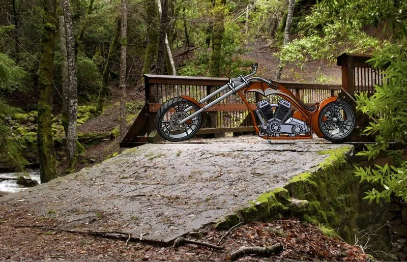
o After adding photoview 360 the render tools tab can be broughtin
o It has various options like preview window, render region, final render, edit
appearance, edit scenes, and options for managing render quality, bloom, cartoon,
direct caustics, network rendering and final image type.
o Schedule render and recall last renders are also some options.
• Final Render photoview:
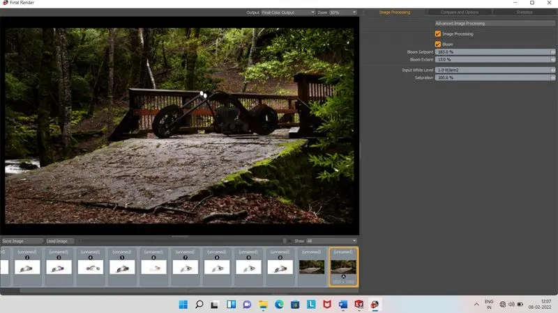
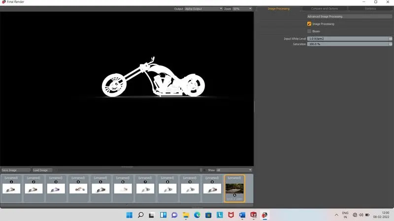
Render Alpha output:
Scheduled render views:
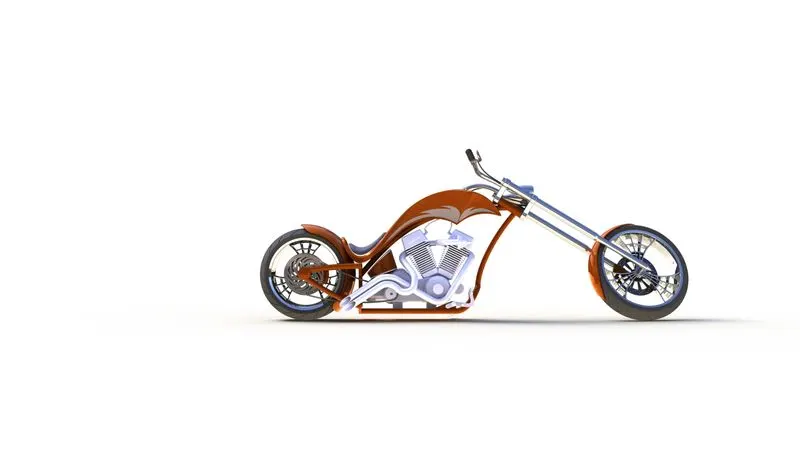
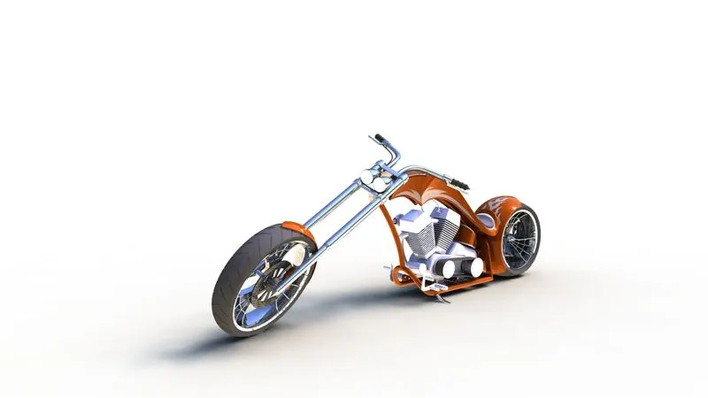
• Some views of assembly renderings:
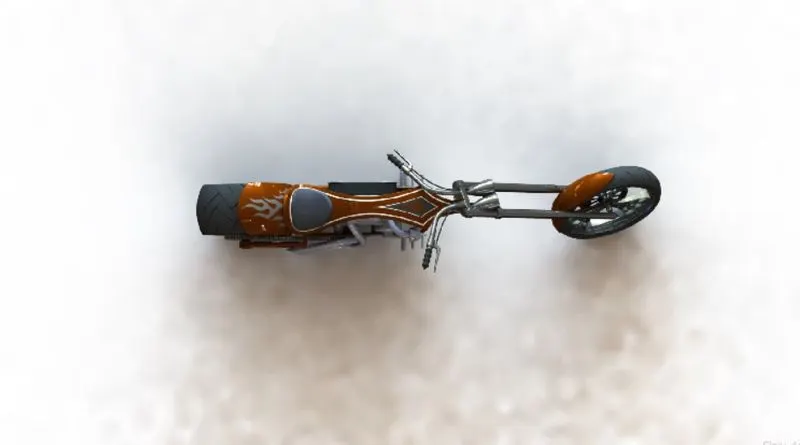
Top view render
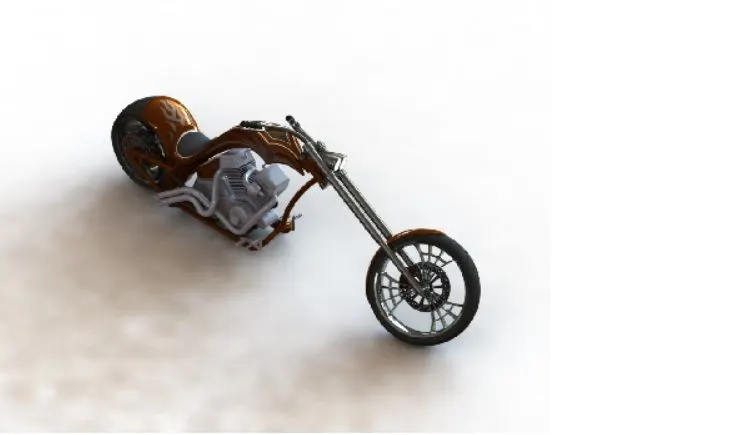
Isometric view render
• Solidworks Visualize environments:
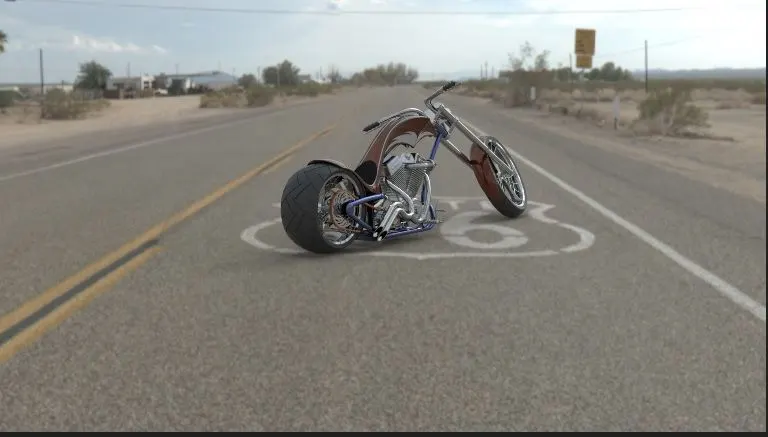
Chopper at Route 66.
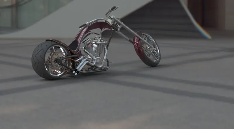
Chopper at Tokyo atrium.
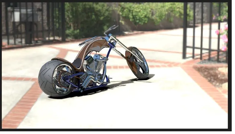
Chopper at sunny driveway.
Conclusion:
Design, Assembly and Photorealistic rendering using solidworks was successfully
completed to make an American Chopper Motorcycle.