Week 8 - Challenge 1 - Draft Analysis on a Fan Cover
AIM: To perform draft analysis and the tooling axis creation for fan cover.
OBJECTIVES:
FAN COVER
- Explaining the draft analysis and tooling axis creation for fan cover.
- Creating the tooling axis particularly the Bisecting method.
ABSTARCT:
DRAFT ANALYSIS: The major consideration of draft analysis is whether sufficient draft angle is provide on the component. Components while designing should be provided with a considerable amount of draft angle depending on the manufacturing consideration. For plastic components we provide a draft angle of 3 degree. But for Automotive sheet metal parts, it will be from 7degree or more.
TOOLING AXIS CREATION: The direction in which the mold or core and cavity opens is the tooling axis. With the help of tooling axis created along x-axis and the y-axis, these tooling axes are used for creating by bisection method. Where two lines and a point will be selected as a input.
PROCEDURE TO PERFORM A DRAFT ANALYSIS AND TOOLING AXIS CREATION IN CATIA
STEP 1
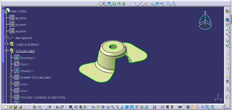
CONNECTIVITY OF CLASS A SURFACE: First check the connectivity of the class-A surface , this can be done by creating boundaries or by using join command and see how well it is connected. Just ensure there is no surface gap between component or surfaces. This is the first design step to check the continuity and the quality of class-A surface.
STEP 2
Analyse visually for the best possible tooling axis for the component.
Checking possibilities in all three X, Y and Z axis directions and finding what are the problem creation parts of the component.
The clearance checking along all the axis direction will be done by creating an intersection along an axis on a plane by creating a new axis system with the model and constructing two lines contact with the walls, the line bisecting the two lines and passing through the point will be tooling axis.
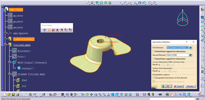
A dummy tooling axis will be directly created using point-direction tool after creating boundary for class-A surface and creating intersection with the model.
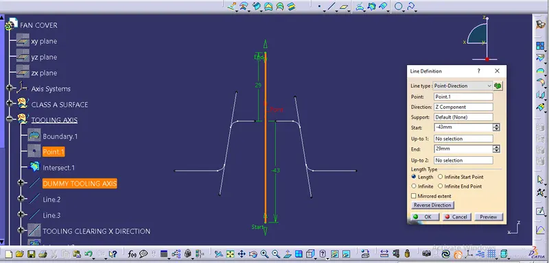
Creating of tooling axis along Y-axis.
Using the intersection created lines will be created along the inclined walls, these lines are used for creation of tooling axis by Bisecting method where are two lines and point will be selected as inputs.
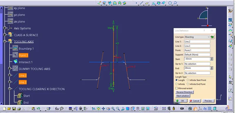
Creating an intersecting lines to check along X-axis.
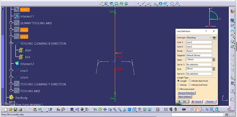
TOOLING AXIS CREATION:
Using the tooling axis created along X and Y-axis, these are used for creation of tooling axis by bisecting ethod where the two lines and point will be selected as inputs.
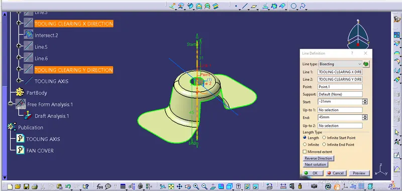
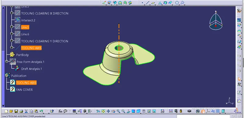
Publication:
Publication is used to make easily accessible of the published comonents.
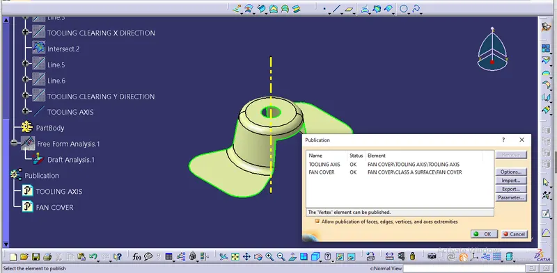
Draft Analysis:
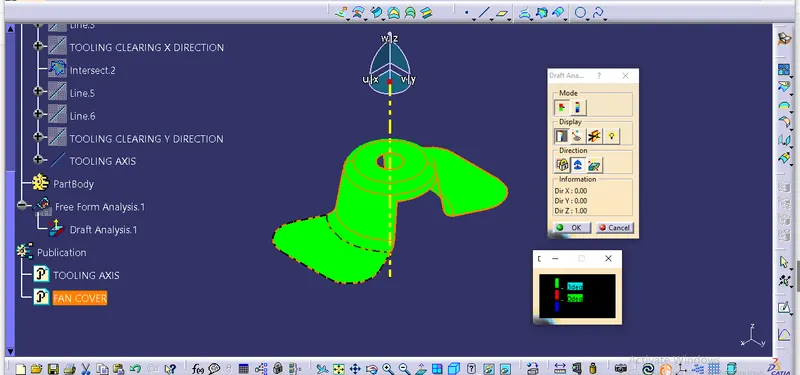
Draft analysis is done after determining the tooling axis, draft analysis is used to check whether the minimum draft 3 degree is maintained or not.
Compass is used to define the draft direction.
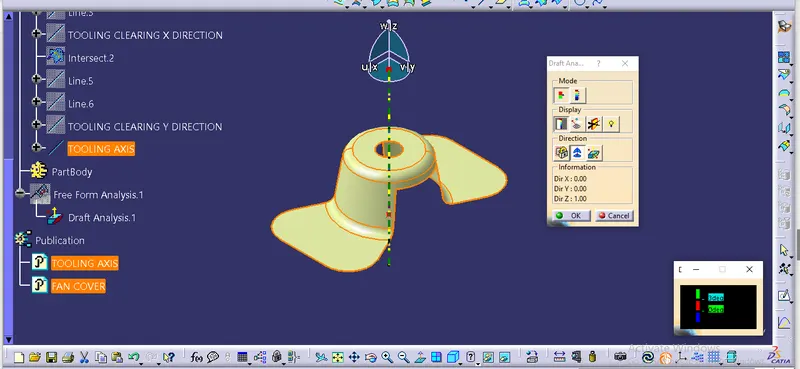
If the minimum draft 3 degree is provided the whole component changes into green colour.
In case of increasing draft angle we can't able to get the exact model what we want for manufacturing.
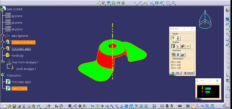
So, in the above image you cann see that, we have change the draft angle to 10 degree. It shows an error for it.
Conclusion:
The above report has clear explanation about using of bisection line method and creating of tooling axis.