Week 8 - Challenge 5 - Core & Cavity Design
Introduction
In automotive design, a class A surface is any of a set of freeform surfaces of high efficiency and quality. Although strictly, it is nothing more than saying the surfaces have curvature and tangency alignment – to ideal aesthetical reflection quality, many people interpret class A surfaces to have G2 (or even G3) curvature continuity to one another (see free form surface modeling).
Class A surfacing is done using computer-aided industrial design applications. Class A surface modellers are also called "digital sculptors" in the industry. Industrial designers develop their design styling through the A-Surface, the physical surface the end-user can feel, touch, see, etc.
A common method of working is to start with a prototype model and produce smooth mathematical Class A surfaces to describe the product's outer body. From this, the production of tools and inspection of finished parts can be carried out. Class A surfacing complements the prototype modeling stage by reducing time and increasing control over design iterations.
Class A surfaces can be defined as any surface, that has styling intent, that is either seen, touched or both and mathematically meets the definition for Bézier.
- Automotive design application
- Product design application
- Aerospace design application
- Clay modeling
- Notable software
Creating B & C Surfaces with the reference of Class A Surface.
Class-A Surface: The top-most surface which is the present exterior of the component is said to be a Class-A Surface
Class-B Surface: The Surface which is interior to the component is said to be a Class-B Surface.
Class-C Surface: The Surface which joins the Class-A & 8 Surfaces is our Class-C Surface
PROCEDURE
- Create a sketch on the ZY plane and the Switch Bezel to create a reference tooling axis.
- Create a sketch on the ZX plane and the Switch Bezel to create a reference tooling axis.
- From the above two reference axis, Bisect the lines to create the TOOLING AXIS.
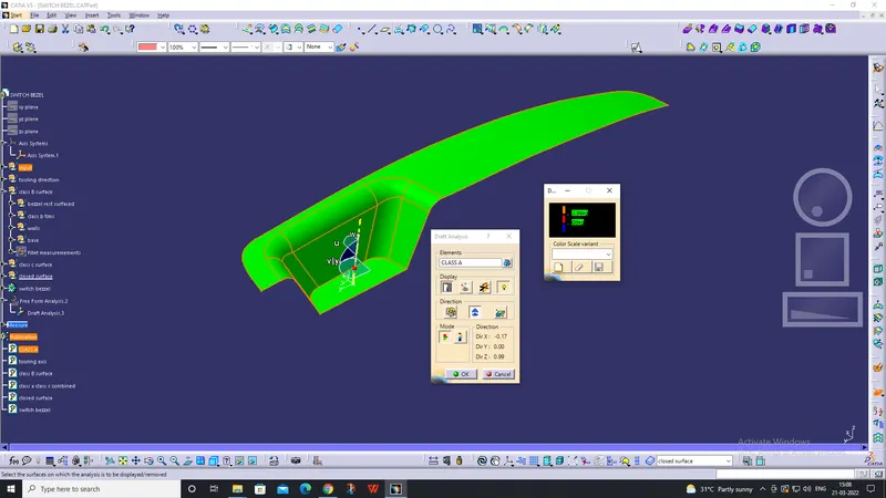
- Draft analysis for the Switch Bezel by quick analysis mode.
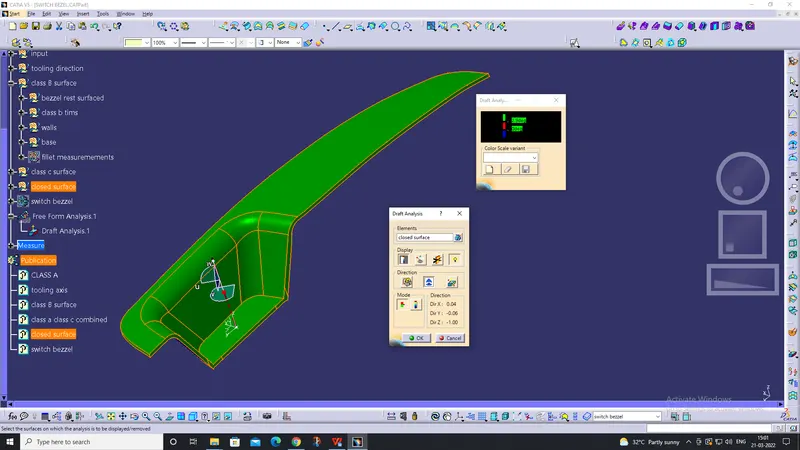
- Draft analysis for the Switch Bezel by Full analysis mode.
- Draft analysis for the Switch Bezel in Isometric view.
- Draft analysis for the Switch Bezel in Front view.
- Draft analysis for the Switch Bezel in Side view.
- Draft analysis for the Switch Bezel in Top view.
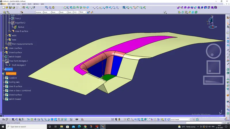
- Class B surface WALLS after extract, Surface Untrim, Extrapolate, Trim.
- Class B surface SWITCH BEZEL ARMREST after Extract, Offset, Surface Untrim, Extrapolate, Trim.
- Class B surface SWITCH BEZEL BASE after Extract, Offset, Surface Untrim, Extrapolate, Trim.
- Final Class B surface.
- Final Class C surface.
- Draft analysis for the Switch Bezel by quick analysis mode.
- Draft analysis for the Switch Bezel by Full analysis mode.
- The final surface of the Switch Bezel with 2.5mm thickness.
- The final surface of the Switch Bezel with Close Surface.
CONCLUSION:-
- A detailed report is been done explaining the draft analysis and the tooling axis creation.
- An explanation is been given on the way of creating the tooling axis by Bisecting method.
- Screenshots of the Draft analysis report.
- Image of the complete Draft analysis.
- Images of the color scale variant.
- Screenshots of the model with the proper color code of the draft angle in various orientations (Isometric, Front, Side, and Top View.
PROCEDURE MOULD DESIGN (CORE AND CAVITY
Core and cavity design:
The Mould Core & Cavity are the shaped sections in either half of the mould tool which give the plastic product its final shape.
The hot molten material is injected into the core & cavity and then sets hard into shape. The design of the core & cavity is essential in the correct formation of the product. The sequence of events during the injection mould of a
plastic part is called the injection molding cycle. The cycle begins when the mould closes, followed by the injection of the polymer into the mould cavity. A core is usually made of the best quality sand and is placed into the desired position in the mould cavity. Core prints are added to both sides of the pattern to create impressions that Now the core to be supported and held at both ends
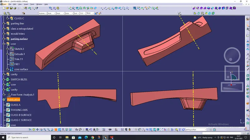
Core:
The core design is started with extracting the parting surface that becomes the datum for the core and cavity The parting surface in most of the cases is kept at the B class surface to avoid close and tight contact between the core and cavity At first, the A-class surface is extrapolated with some length and later it is trimmed with a C surface.
A and C are trimmed with B surface
now final block is made after extruding a rectangular sketch around previous trim and opend surface is closed by fill or multisection
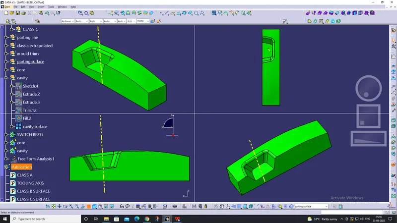
Cavity:
The cavity is the part where the injector and filling of the molten plastic happens. The cavity block is prepared by first extruding the outer boundary along the tooling direction
This outer surface is trimmed with the B class surface and then it is filled and thickened.
Parting line and Parting surface:
A parting line, in the industrial casting of molds is the borderline in which draft angles change direction. That is it is the dividing line that splits the core and cavity halves of a molded part, it is sometimes a starting point for the mold Here intersecting the parting surface, core, and cavity across the ZX plane gives the intersecting line that tells the parting line.
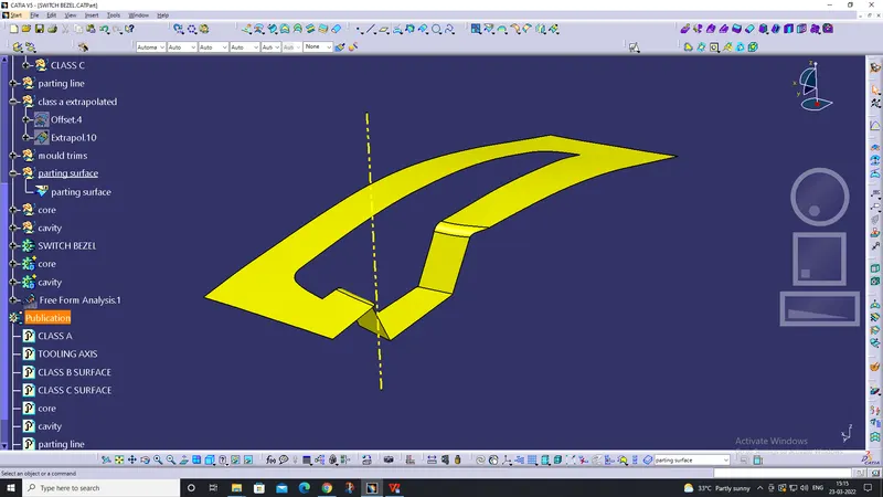
Parting surface:
The parting surface of a mould are those surfaces of both mould plates adjacent to the impressions which butt together to form a real and prevent the loss of plastic material from impression, the parting surfaces of a mould are those portion of both mould plates, adjacent to the impressions, which butt together to form a seal and prevent the loss of plastic material from the impression
tooling axis
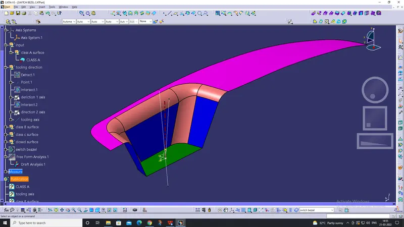
Class A draft analysis
class b surface after untrim , extrapolating and trimming
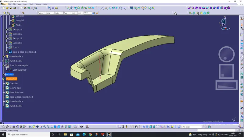
class c before trimming
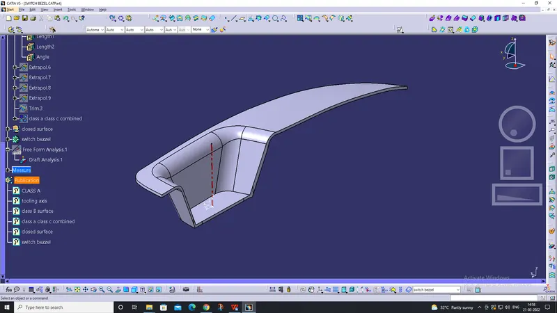
final draft analysis
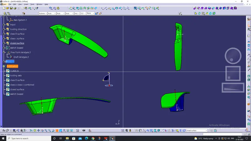
parting line and tooling axis
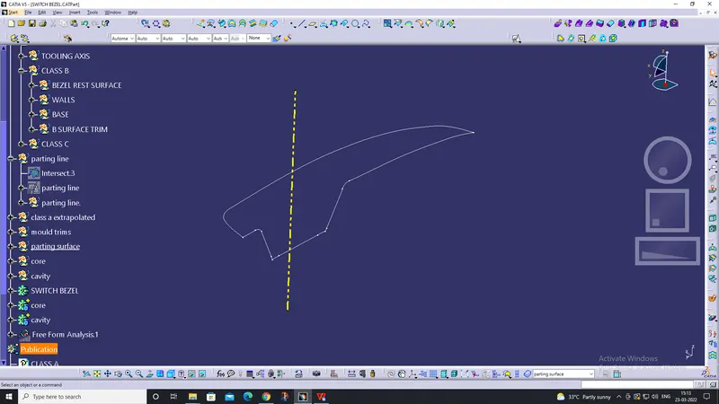
A ans C trimed with B surface
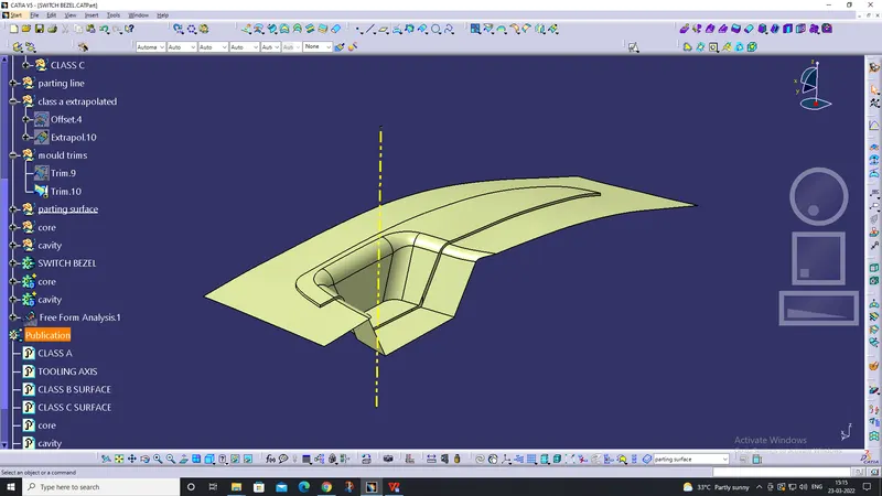
Parting surface
Core block and its different views
Cavity block and its different views
core and cavity translated to get better undersanding
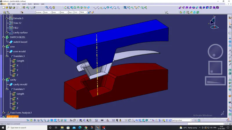
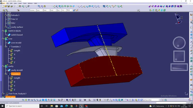
final picture with Core Cavity parting line and surface and tooling axis
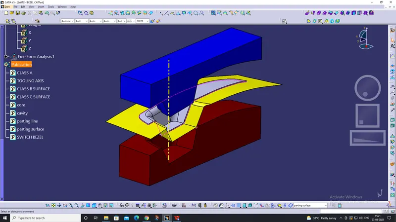
Conclusion- Mould is made switch bezzel using core and cavity