Week 8 - Challenge 2 - Base Bracket Design
Intoduction:
In automotive design, a class A surface is any of a set of freeform surfaces of high efficiency and quality. Although strictly, it is nothing more than saying the surfaces have curvature and tangency alignment – to ideal aesthetical reflection quality, many people interpret class A surfaces to have G2 (or even G3) curvature continuity to one another (see free form surface modelling).
Class A surfacing is done using computer-aided industrial design applications. Class A surface modellers are also called "digital sculptors" in the industry. Industrial designers develop their design styling through the A-Surface, the physical surface the end-user can feel, touch, see etc.
A common method of working is to start with a prototype model and produce smooth mathematical Class A surfaces to describe the product's outer body. From this, the production of tools and inspection of finished parts can be carried out. Class A surfacing complements the prototype modelling stage by reducing time and increasing control over design iterations.
Class A surfaces can be defined as any surface, that has styling intent, that is either seen, touched or both and mathematically meets the definition for Bézier.
- Automotive design application
- Product design application
- Aerospace design application
- Clay modelling
- Notable software.
BASE BRACKET DESIGN
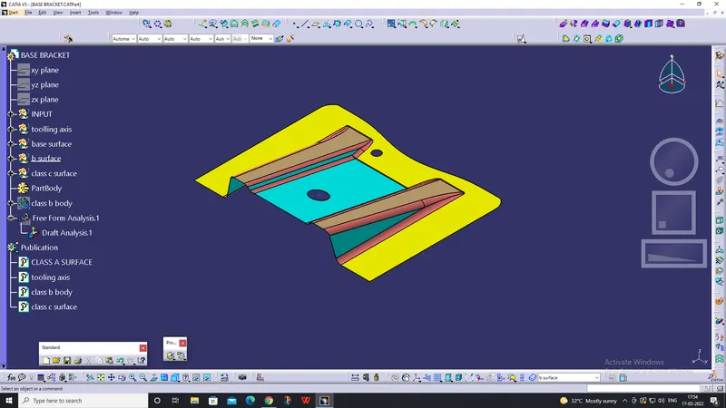
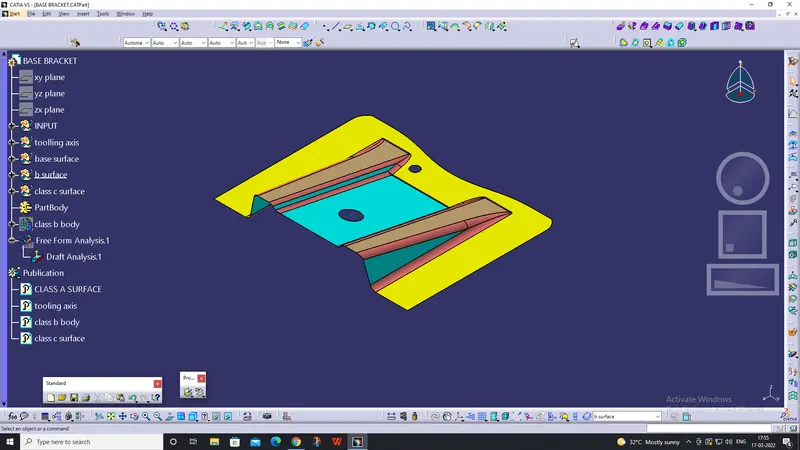
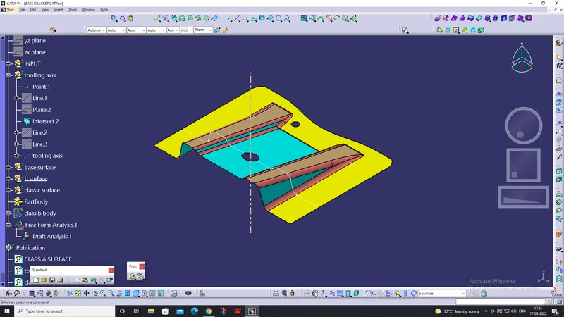
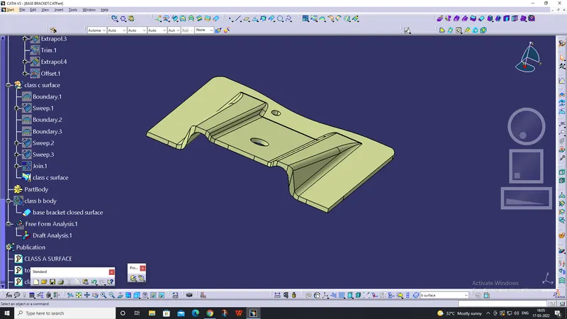
Creating class B & class C Surfaces with the reference of Class A Surface given in the question.
Class-A Surface: The top-most surface which is the present exterior of the component is ca be a Class-A Surface
Class-B Surface: The Surface which is interior to the component is said to be a Class-B Surface.
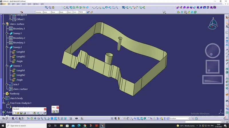
Class-C Surface: The Surface which joins the Class-A & 8 Surfaces is our Class-C Surface
Procedure:
Step-1:
- Create an axis for the component for which the component should move in the tooling axis.
- For that, take an axis system and make an intersection to the corresponding plane.
- Then make a bisecting line to that intersection and make that line your tooling axis
- From that tooling axis, were gonna make Class B & C Surfaces;
Step-2:
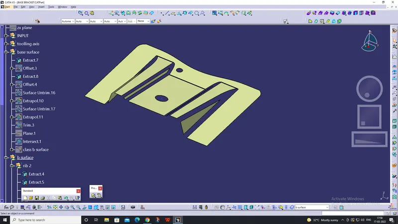
- After taking your tooling axis, take the Class-A Surface as the reference to make Class-8 Surface.
- First, take a Geometrical Set and rename it as Class-B Surface and work it from there.
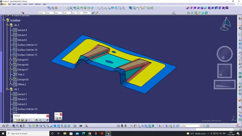
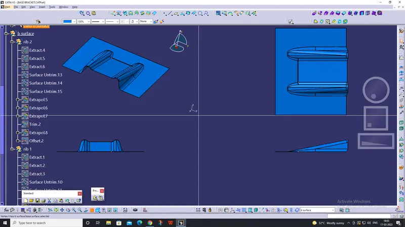
- Then divide the Class-A into simpler geometry. First, take the two ribs and work on them.
Step-3:
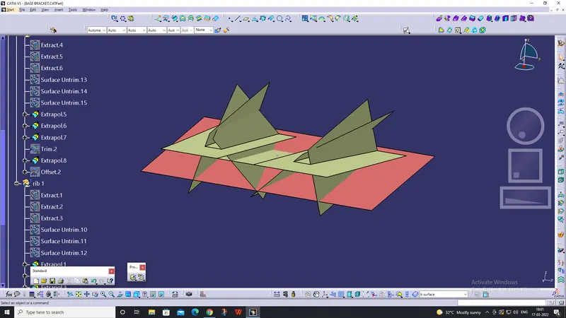
On the first rib, Extract the three surfaces which act as a rib.
Step 4:
After Extracting, Untrim the surfaces and extrapolate it with point continuity.
Step-5:
Trim those extrapolate and make it as a single component (rib)
Step-6:
Make an offset to the trimmed component (rib) of 2.5mm downwards Do the same process for another rib, slope surface and base surface also
Step-7:
Trim those four surfaces and make it as a single component (Class-B).
Stop-8:
Make fillets to your surface according to your thickness and Class-A Surface
Step-9:
The next step is to make Class-C Surface from Class-A
Take boundary to your Class-A & sweep the curve to the draft direction.
And Make the entire Class-A to the Class-C Surface.
Step-10:
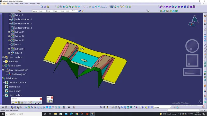
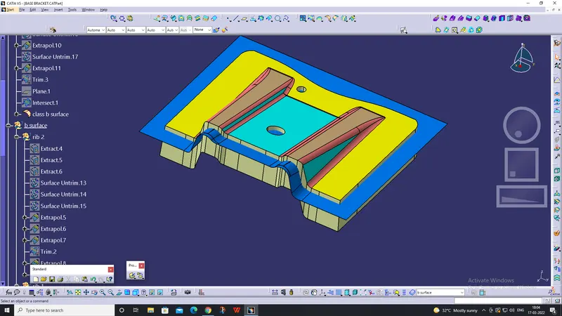
Now, Trim the Class-B & Class C Surfaces to get a component that joins to your Class-A and makes as a final component
Step-11
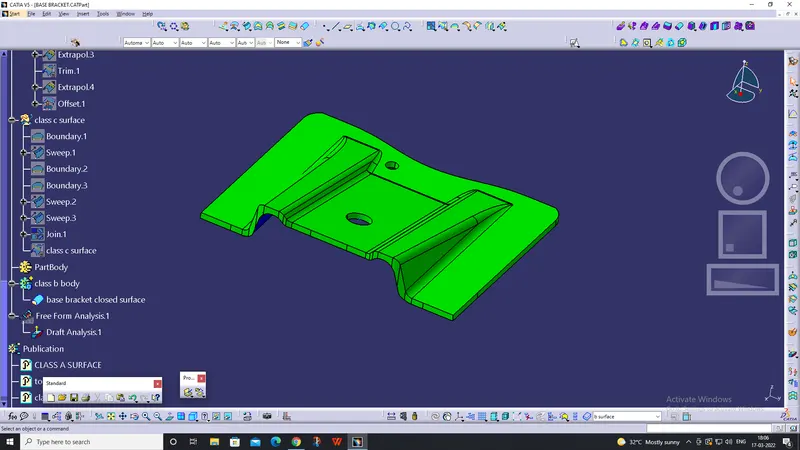
The last step of your component is to make a solid body by going into Part Workbench and doing the Closed Surface command. Then you obtain your PartBody
Step-12:
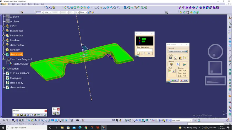
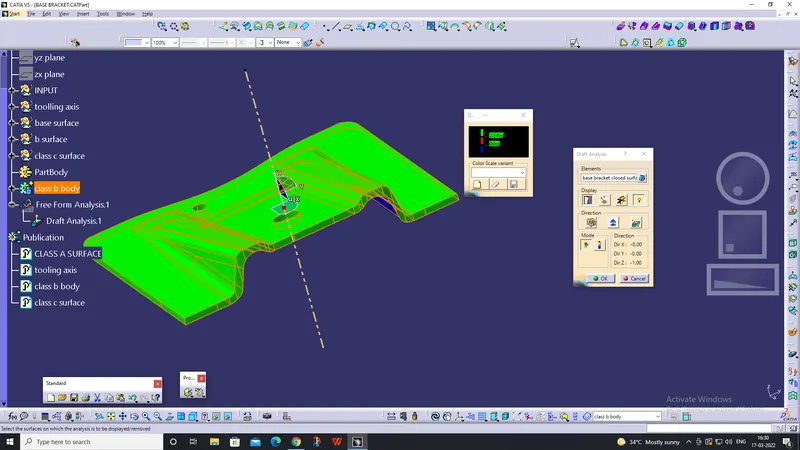
After making it as a complete body, do draft analysis and ensure the body is manufacturable.