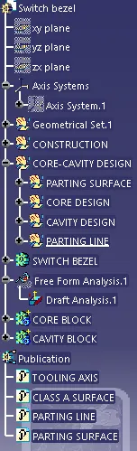
Week 8 - Challenge 5 - Core & Cavity Design
OBJECTIVE:Create the Core and cavity blocks for the switch bezel designed in the earlier challenge.
DETAILED REPORT
CLASS A SURFACE: Class-A is a term used in specifically in automotive design. It describes the final production surface data for the aesthetic parts of the car.
CLASS B SURFACE: This surface is created by taking the offset fom the class A surface and it is the surface on which all the mountings and ribs are created
CLASS C SURFACE: It is the surface which joins class A and class B together
TOOLING AXIS: It is the direction in which core and cavity opens & closes
The parting surfaces and core/cavity blocks are created based on the parting direction and parting lines
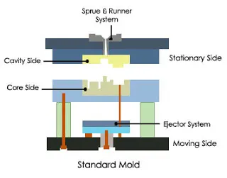
Cavity and core plate
- The core is the which forms the internal shape of molding. The cavity is the which forms external shape of molding.
- These two parts is very important in the mould. It can affect the products shape and quality of the products.
- The core & cavity are the shaped sections in either half of the mould tool which give the plastic product its final shape. The hot molten material is injected into the core & cavity and then sets hard into shape.
PARTING LINE
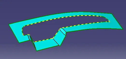
- parting line that splits the mold into two parts – the core and the cavity
- A parting line, in industrial casting of molds, is the border line in which draft angles change direction. One can check the parting line in the mould or product which divides the two half, i.e; the core and the cavity of a molded part. It is sometimes a starting point for the mold parting surface
PARTING SURFACE
- A parting surface is a surface that separates the mold block into two parts – the core and the cavity
- The two half are pressed tightly and form a sealed hollow to avoid the melt flow leakage and maintain Certain holding pressure, the pressed surface is called parting surface
Parting surface design principles
It directly affects the product quality, ease of construction and operation of the injection mold ,the mold design is one of the key factors to success
Design parting surface should follow following principles:
1. Design the injection mold structure as simple as possible. Avoid side parting as simple as possible to reduce the complexity of mold making.
2. Ease of de-molding as far as possible. The plastic parts should stay in fixed haulf of the injection mold and ejected by ejection system avoid dude de-modelling function.
3. Ensure the dimensional accuracy of the molded parts. Try to make the parts with same dimensional accuracy requirements with same dimensional to reduce manufacturing and assembly errors.
4. Ensure apperance requirements of the molded parts . Flash or mismatch occurs usually on parting surface, so the parting surface souls not be designed on an high quality requirement surfaces.
5. Ensure adequate wending . If possible, parting surfaces to be placed at the end of mold flow.
DRAFT ANALYSIS
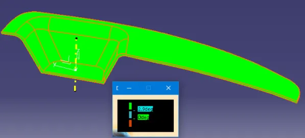
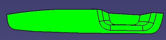
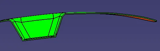
- Go to feature draft analysis and Align the tooling axis with the compass
- Click on the surface and see that the surface was with in the permissible limit of draft analysis and If any surface is not green we have to edit our tooling axis
CORE DESIGN
Extrapolate the class A surface
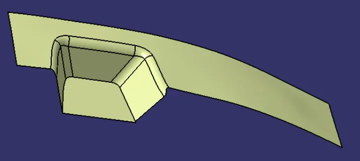
Trim the extrapolate class A with class c to get inside portion
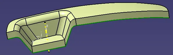
Now trim the b surface with output of class A and class c that will be parting surface with respect to area
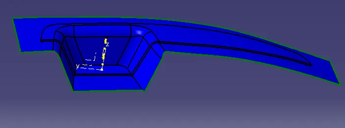
Extrude the sketch overall through the tooling direction and trim it with parting surface
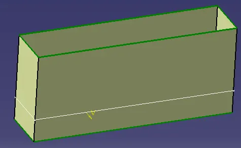
trim the extrude with parting surface with component area
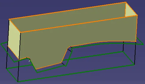
fill the top surface and join both and Final out of core design
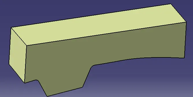
CAVITY DESIGN
Similarly trim the extrude with class B surface
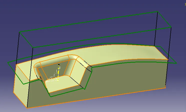
fill the top surface and join both ,Final out of cavity design
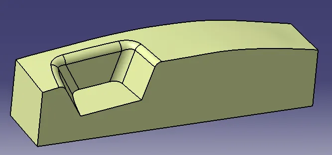
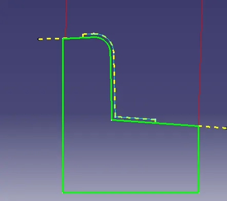
Check the surfaces by using intersect
SOLID BODY
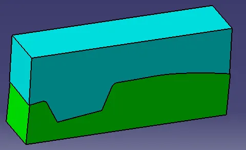
solid body was created by using closed surface in part design.final closed surfaces of cavity and core
isometric view
front view
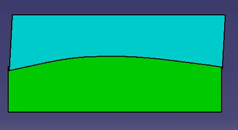
side view

PARTING LINE AND PARTING SURFACE
PART BODY