Week 8 - Challenge 5 - Core & Cavity Design
CORE AND CAVITY DESIGN OF SWITCH BEZEL
Draft is the angle that is put on the side faces of the part so that the part doesn’t get trapped in the mold or cast. Here the draft angle is checked on switch bezel in CATIA V5.
The Class A surface is provided to us.

Fig 1. Class A Surface
First of all we need to check whether the surface provided has nay discontinuity in it. For that we will use the command boundary and check if there is any discontinuity in the surface.
After that we will join the whole surfaces of the fan cover by using join command.
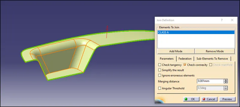
Fig 2. Join Command
Then we will randomly select the tooling axis. For making the selection first analyse the shape of the product and avoid side cores as far as possible. Here we will take the Z axis as the tooling direction and mark a point there and create a datum axis at that point. We will make a dummy tooling axis in the Z direction.
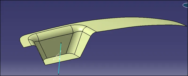
Fig 3. Dummy Tooling Axis and datum axis is created
Next step is to take the intersect of the Class A Surface and the YZ plane.
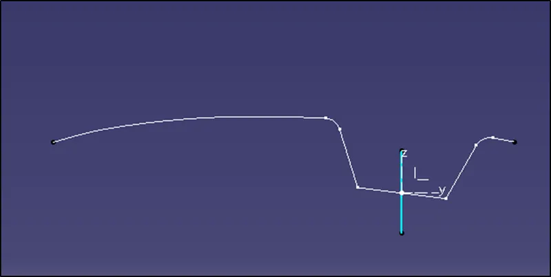
Fig 4. Intersect at YZ plane.
Observe the surfaces which are parallel to the dummy tooling axes and which will create a problem while the component will be ejected from the mould. Draw a line through the surfaces.
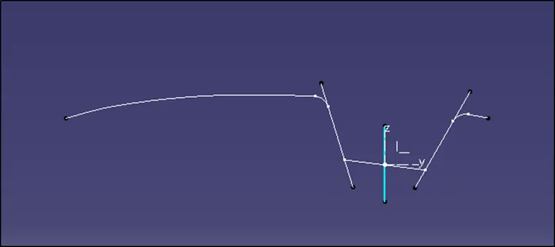
Fig 5. Extending the parallel surfaces to the dummy tooling axis
Next bisect both the lines and obtain the line that is going in the direction of the dummy tooling axis. That will be the tooling axis in the YZ direction.
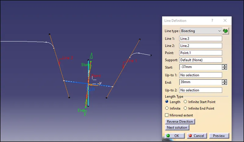
Fig 6. Bisecting the lines
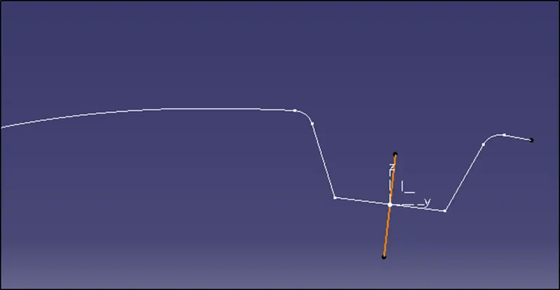
Fig 7. Tooling axis in the YZ direction
Next obtain the tooling axis for the XZ direction by following the same steps.
Take the intersect of the switch bezel and the XZ plane. Identify the faces which are parallel to the dummy tooling axis. Since there is only one face which will create a problem in the removal of the component. We will sketch another line which is at an angle to the surface.
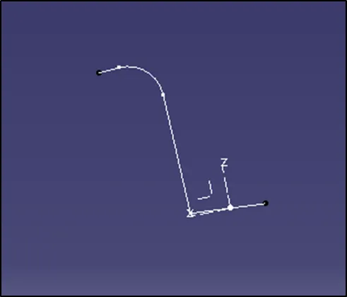
Fig 8. Intersect at XZ plane
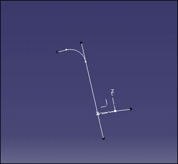
Fig 9. Extending the surfaces parallel to the tooling direction.
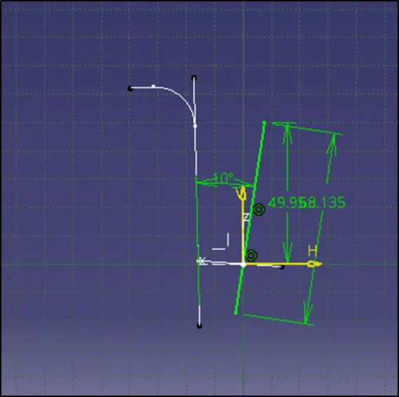
Fig 10. Sketching a line at an angle to the surface
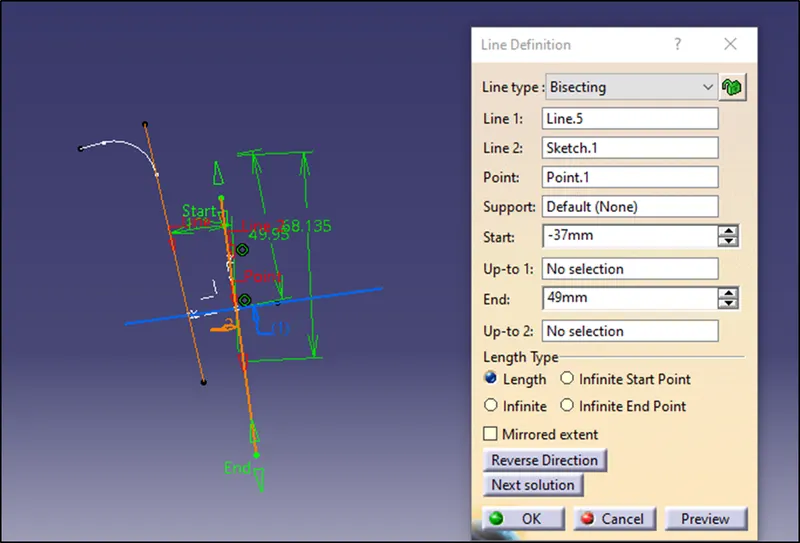
Fig 11. Bisecting the lines
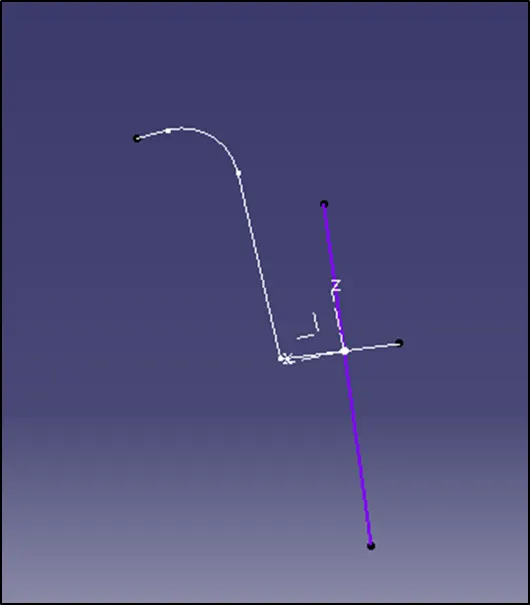
Fig 12. Tooling axis in the XZ direction
Now we have got tolling axis in the XZ and YZ direction. Bisect both the lines and obtain the line which is in the direction of the dummy tooling axis. That is the required tooling axis of the Switch Bezel.
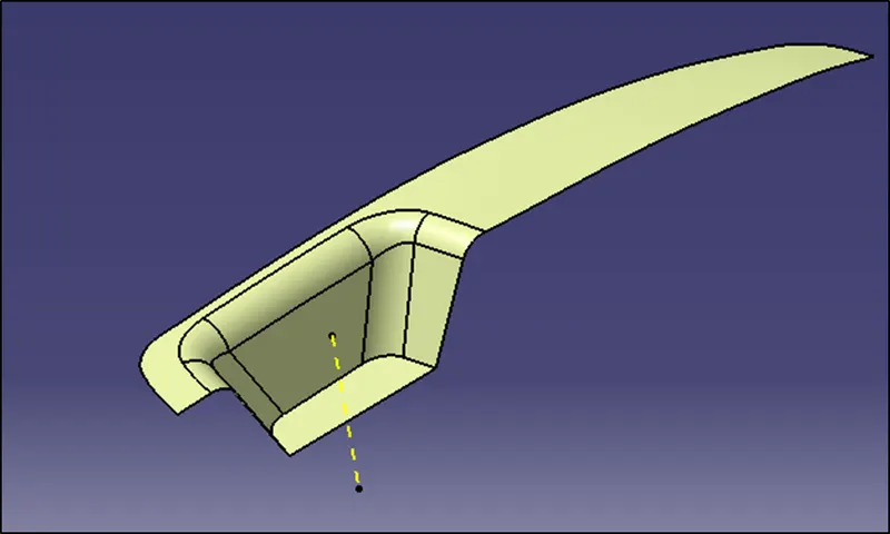
Fig 13. Tooling axis
Now we have to perform the draft analysis in the required tooling direction.
Change the view to material mode in the customize view parameters.
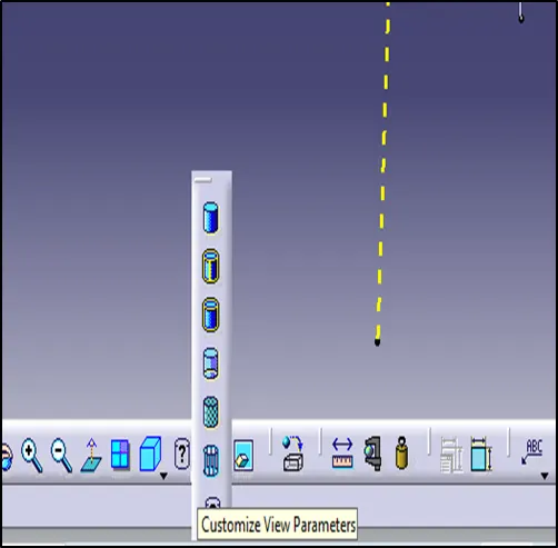
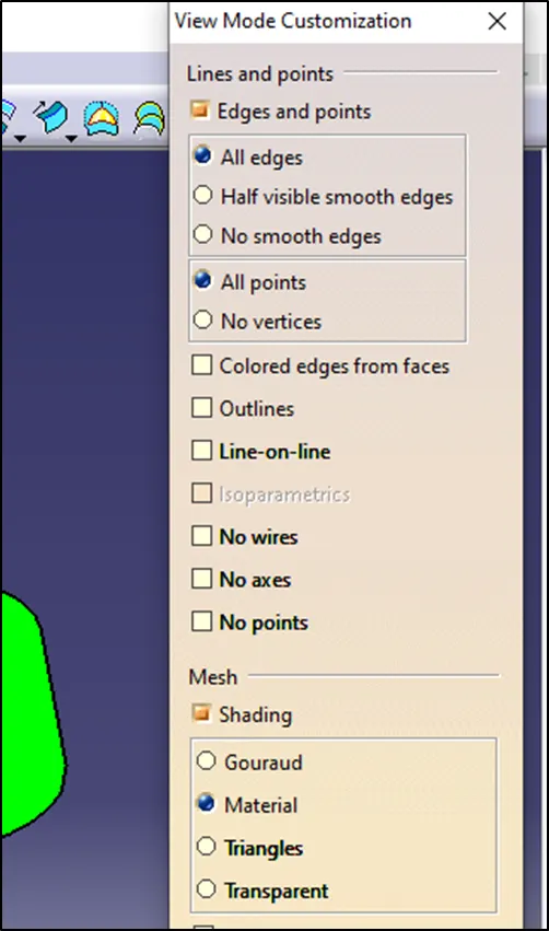
Fig 14.Material Mode for Draft Analysis
Then insert > analysis > feature draft analysis
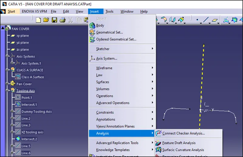
Fig 15.Draft Analysis
Next take the compass and put it over the tooling axis to get the required direction of draft analysis and then lock the draft direction.
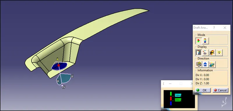
Fig 16. Compass over the tooling axis
Then double click on the component and it will show the draft analysis. It is shown according to different colours for different draft angles.
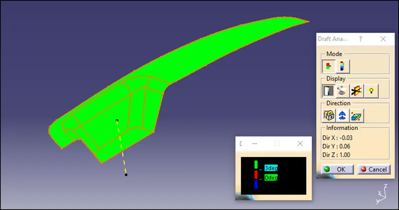
Fig 17. Draft Analysis
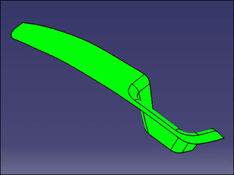
Fig 18. Isometric View
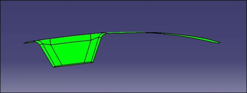
Fig 19. Front View
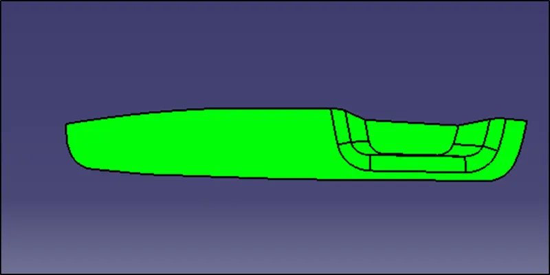
Fig 20. Top View
Draft analysis for Final Solid:
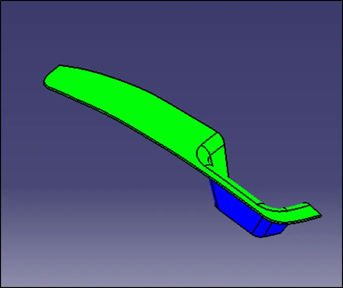
Fig 21. Isometric View
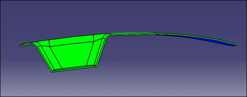
Fig 22. Front View
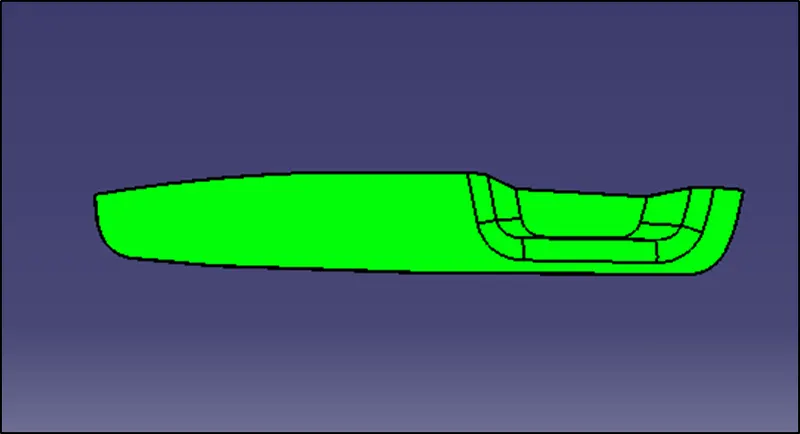
Fig 23. Top View
CORE AND CAVITY DESIGN:
The Mould Core & Cavity are the shaped sections in either half of the mould tool which give the plastic product its final shape. The hot molten material is injected into the core & cavity and then sets hard into shape. The design of the core & cavity is essential in the correct formation of the product.
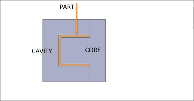
Fig 24. Core and Cavity
Now to create the core and cavity of the component first we have to analyse the component and see which part will be core and cavity. In switch bezel the upper part will be the core and the lower part will be the cavity.
To create the core extrapolate the class A surface and trim it with C Surface. Then Trim the surface with the B Surface which is the parting surface.
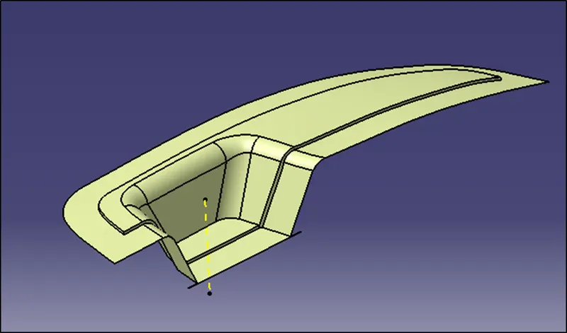
Fig 25. Surface for Core Design
Parting Surface:
The parting surface of a mould are those surfaces of both mould plates adjacent to the impressions which butt together to form a seal and prevent the loss of plastic material from the impression.
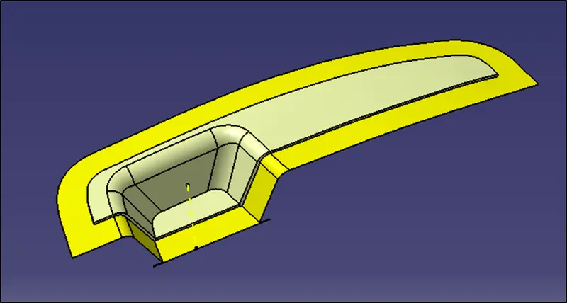
Fig 26. The area marked in yellow indicates Parting Surface
After creating the surface for the core draw a rectangle shape on the parting surface.
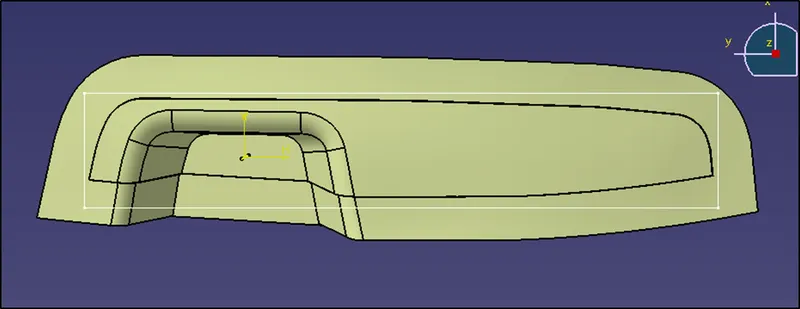
Fig 27. Rectangle shape for the core.
Extrude the rectangle in the direction of the tooling axis and trim the lower part and the parting surface to get the required shape and close the surface to make it solid.
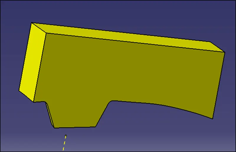
Fig 28. Core Block
Cavity Design:
For Cavity design, take the parting surface and extrude the rectangle in the direction of the tooling axis. Trim the rectangle shape and the parting surface to get the required shape.
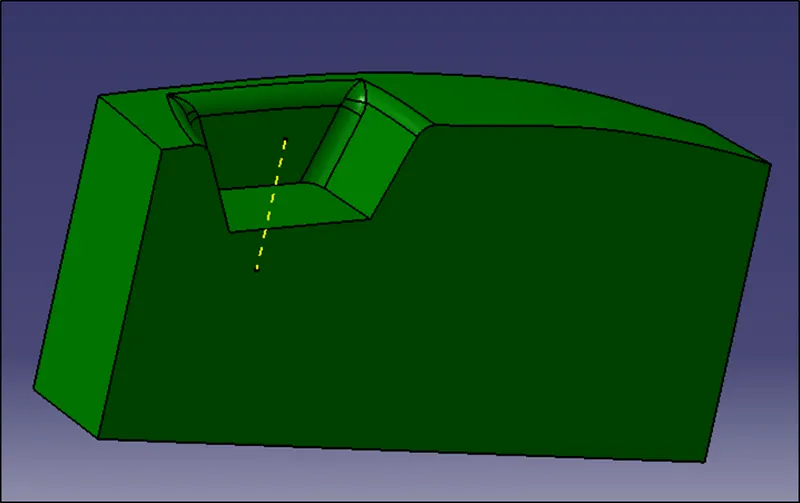
Fig 29. Cavity Block
Parting Line:
A 'parting line' is the line of separation on the plastic part where the two halves of the plastic injection mold meet. The line actually indicates the parting 'plane' that passes through the part.
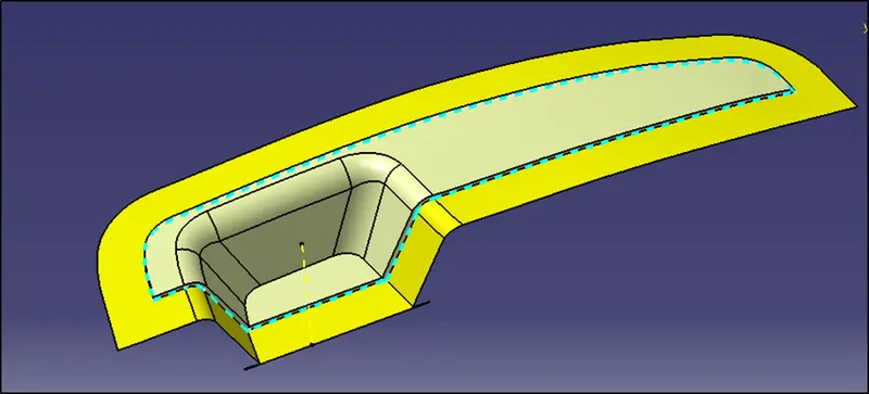
Fig 30. The blue dotted line indicates the Parting Line
If we take the section view then we can see a small gap where the mould gets filled with plastic.
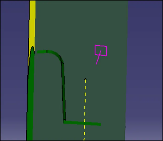
Fig 31. Gap where the plastic gets filled
Views of the Core:
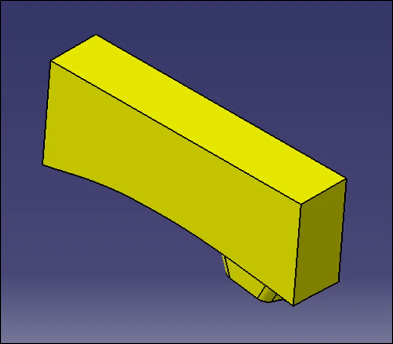
Fig 32. Core Isometric View
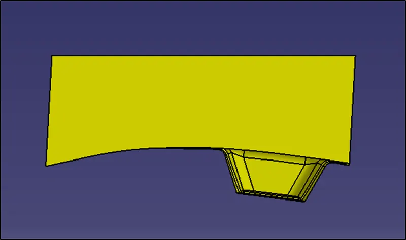
Fig 33. Core Side View
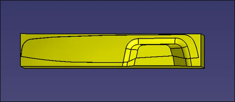
Fig 34. Core Bottom View
Views of the cavity:
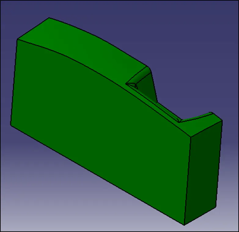
Fig 35. Cavity Isometric View
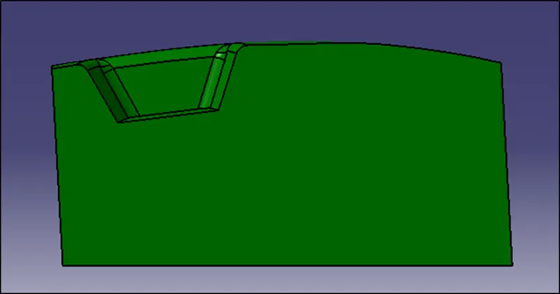
Fig 36. Cavity Front View
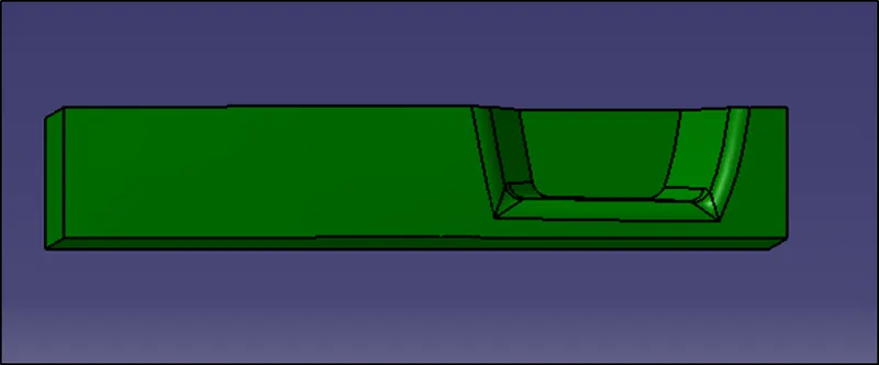
Fig 37. Cavity Top View
************