Advanced Sheet Metal Design Using NX Cad Challenge_1_Casing Design
PROJECT REPORT
TITLE: DESIGN OF SHEET METAL CASING IN NX CAD
OBJECTIVE: To design and model the casing in sheet metal workbench of NX CAD version 11.
INTRODUCTION: NX is a 3D CAD CAM software developed by Siemens. The Casing will be designed and modelled in the sheet metal workbench of the NX.
Sheet Metal is a metal formed by an industrial process into thin, flat pieces. It is one of the fundamental forms used in metal working and it can be bent into variety of shapes. Countless everyday objects are fabricated from sheet metal. The thickness can vary significantly, extremely thin sheets are called foils and sheets having thickness greater than 6mm are called plates.
DESIGN METHODOLOGY:
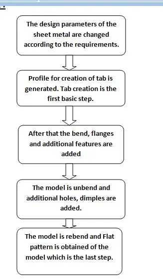
DESCRIPTION:
The tools and features used in the design and modelling of the casing are:
Tab:
It is the first basic feature of the sheet metal design. It is actually the base of the model on which additional features are added. First the profile for the tab is generated and by using the tab command the tab is created.
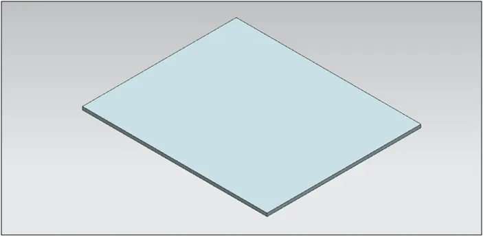
Fig 1. Generation of Tab
Normal Cut out:
It is the type of cut out which is mainly preferred in sheet metal design. The advantage this type of cut out has over the extrude cut out is that normal cut out removes the material perpendicular to the surface of our model rather than plane.
First the sketch is generated and using the normal cut out the material is removed from the part.
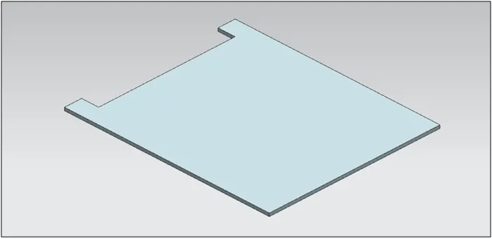
Fig 2. Normal Cut out
Bend:
The sheet metal is given the required bend to obtain the required model. The sketch for the bend is generated and using the bend command and changing the parameters the required bend is obtained.
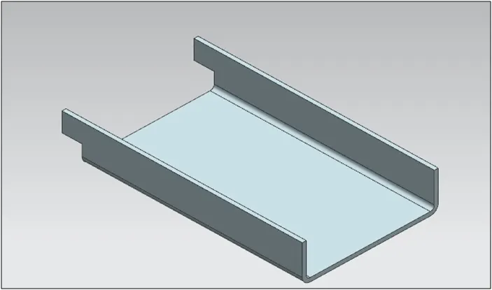
Fig 3. Bend
Flange:
Flange is a projecting rim on a flat object. Flanges can be given to the edges of the model by using the flange command available n the sheet metal workbench.
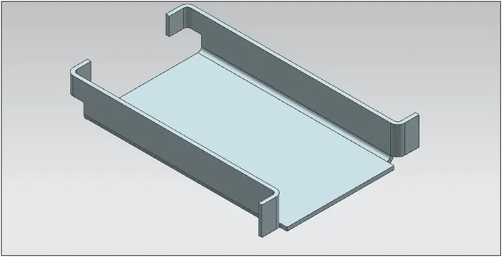
Fig 4. Flanges
Break Corners:
It is a feature which is given to the sharp corners to make it smooth.
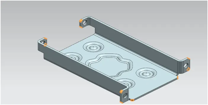
Fig 5. Break Corners
Unbend:
The part is unbend to create additional features such as hole, dimple, beads which otherwise cannot be created if it not unbend. Moreover it also helps to check whether the part is a sheet metal or not. If the part is unbending then it is a sheet metal otherwise it is still a solid body or dumb body.
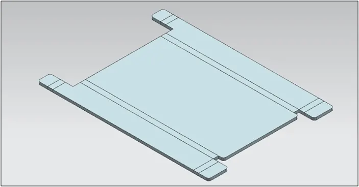
Fig 6. Unbend
Hole:
The plane or the sketch is selected for the hole to be given and from the hole feature available in the sheet metal workbench, the parameters are filled in and thus the hole is generated.
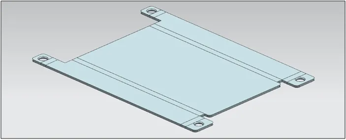
Fig 7. Hole
Beads and Dimples:
Beads and dimples are given in the sheet metal to provide strength to the sheet metal parts. The sketch profile for the bead and dimples are created on the required sketch plane.
The options for the bead and dimple are available in the sheet metal workbench. The required parameters are entered and thus bead and dimples are created.
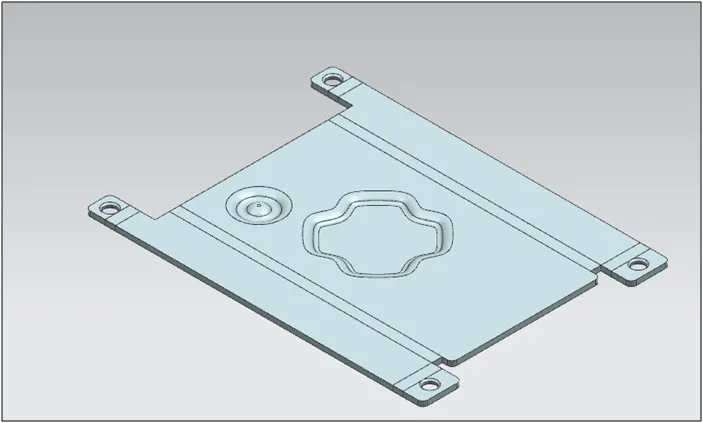
Fig 8. Bead and Dimple
Mirror:
It is the feature which helps to create to exact copies of the body by selecting a reference axis or plane. Mirror option is available in the sheet metal workbench of the NX CAD.
Select the bodies or features which are to be mirrored and select a plane or axis about which the feature or body is to be mirrored.
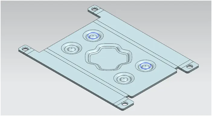
Fig 9. Mirror
Rebend:
After creation of additional features the part is rebend back to get our required product.
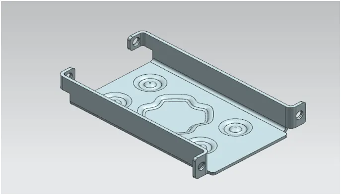
Fig 10. Rebend
Flat Pattern:
It is the last step of the sheet metal design. The created model is flattened out to know the exact length of the blank required for its manufacturability. By selecting the flat pattern the view of flat pattern is created and this view is added in the drawing sheet.
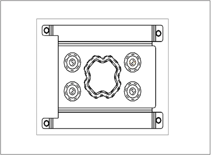
Fig 11. Flat Pattern
A lot of information can also be added in the flat pattern view for the help of the tooling engineer or for the production engineer. The bend table depicting all the bends can be added in the view.
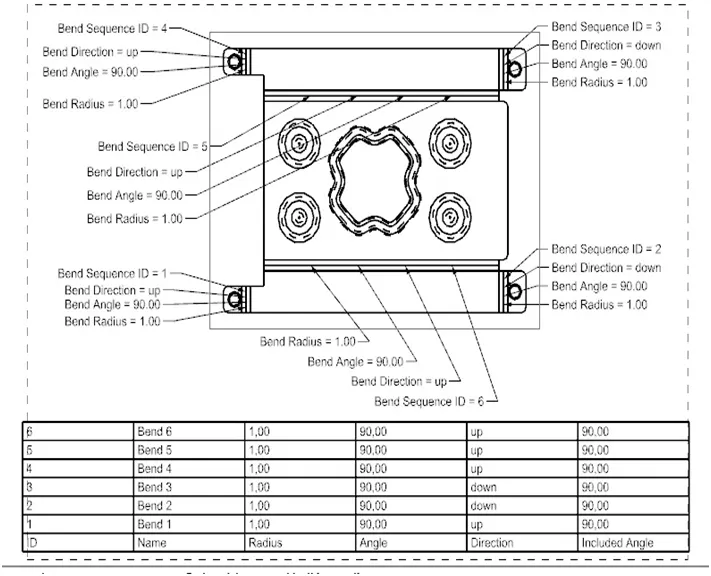
Fig 12. Flat Pattern With Complete information
MODEL VIEWS:
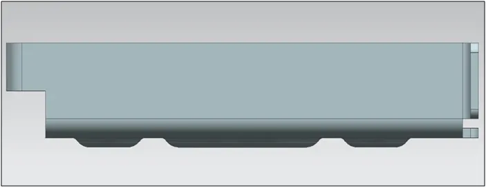
Fig 13. Casing Front View
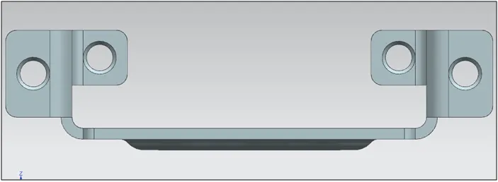
Fig 14: Casing Side View
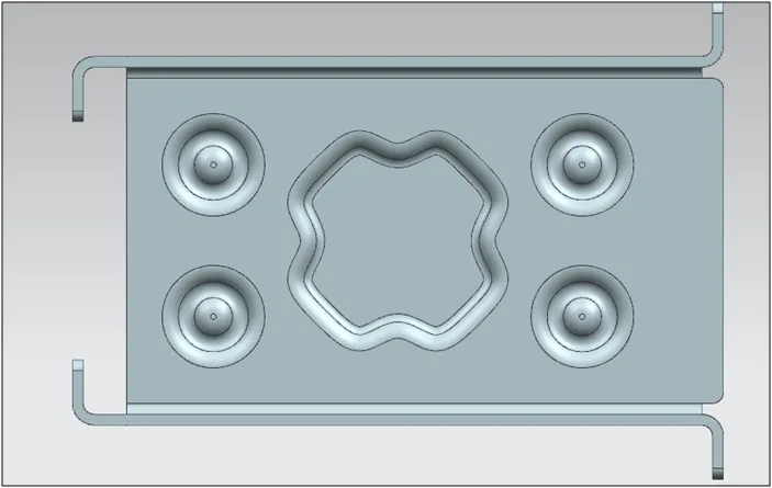
Fig 15. Casing Top View
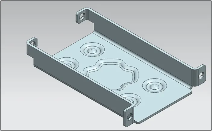
Fig 16. Casing Isometric View
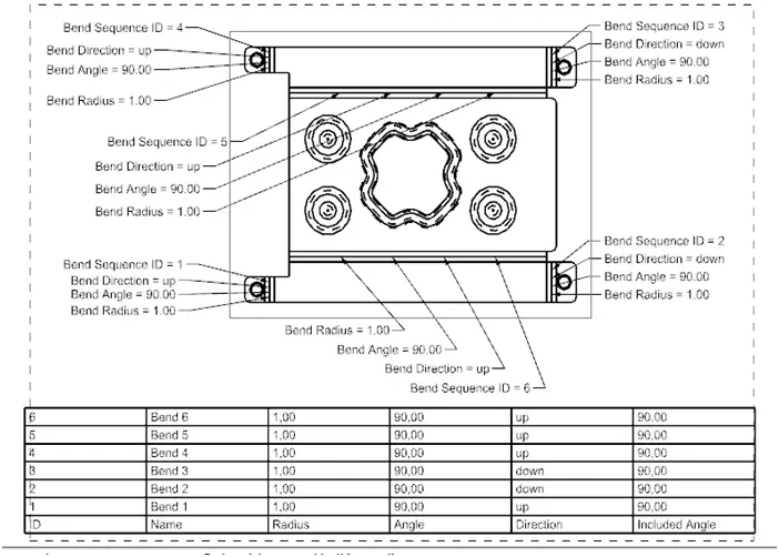
Fig 17. Detailed Drawing Sheet
CONCLUSION:
- This project helped me to understand the basic features of the sheet metal workbench in NX CAD.
- Got familiarised with the user interface of the NX CAD.
- Understood the various terminologies realted to the sheet metal design.
********