Week 8 - Challenge 5 - Core & Cavity Design
The Core and cavity blocks with Design and Draft analysis of switch bezel:
Objective:
The objective of the product is to design the switch bezel and to do a draft analysis for it by creating the required tooling direction with the help of bisecting method.
Introduction:
The control panel bezel is the frame part of the window switch that holds its switch covers and buttons into place. Molding is the method used to manufacture the plastic trims of an automotive by most OEMs hence by considering the manufacturing The switch bezel is designed.
Design consideration:
Class-A surface should be aesthetically smooth and good.
Class-B surface should have all the supporting features like Ribs.
Parting should coincide with the B-surface since flashing couldn’t affect the aesthetic of class-A
Class-C surface Should also pass the draft analysis.
Procedure:
First, the given stylish surface is checked for any irregularities and if found and then it I corrected by using trim, extrapolate, split, and join commands.
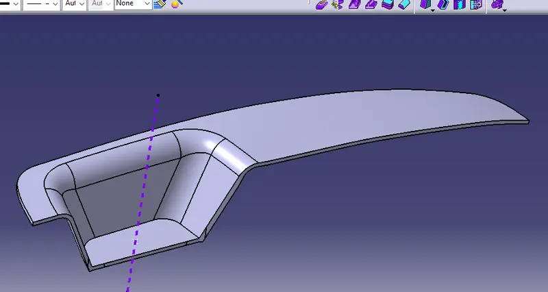
The below images shows that the class A surface is clean and no irregularities present, so let’s move on to the next step.
Creation of tooling direction:
Considering the ejection from the cavity of the mold after manufacturing the interior trim must have the nominal 3 deg draft angle.
Hence the tooling direction is created by considering the above factor and bisecting method is used.
The base surface of the class A was extracted and a point at the center is created and an axis system was inserted into the point with the current feature is disabled.
Then using projection intersection along YZ plane is created and the two inclined lines were drawn inside the positioned sketch.
Then bisecting lines with the two inclined lines were drawn.
Now the same procedure done along the XY plane but one side we don’t have inclined lines so the center point is used to extrude a line along the Z-direction and gave a measurements of 4 deg.
With these two lines from sketches 1 and 2, The bisecting line is created and published as tooling axis.
Creation of class-B surface:
For creating the class-B surface the required surface except the offset surface have been extracted and then untrimmed all the surface.
Then all the surface has been extrapolated to get intersections between them.
Since the thickness of the switch bezel is 3mm.
Creation of class-C surface:
The required outer edges of the A-surface were extracted using multiple Extract. Then for avoiding the patches the curve is smoothened using the smooth curve option. Then by using the sweep command the surface was created.
After using the extrapolate command the edges were intersected between the surface corners which eases the trimming operation. Now the required portion of the C-surface were trimmed out.
Creation of closed surface:
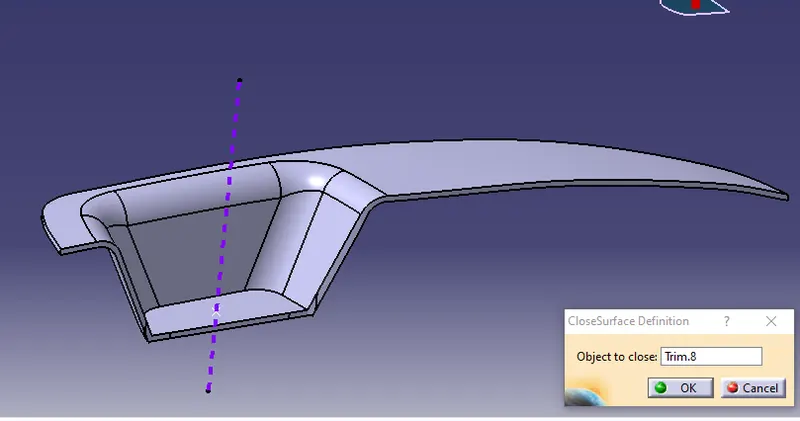
Now the class A and class C surfaces joined together by removing the gaps in-between them with the help of extrapolation and trim surface, Then the exact surface of the switch bezel was trimmed from the above resulted trim surface with the class B surface.
Then by defining the part body by using the closed surface command in part design, the components solid body is created.
Draft analysis:
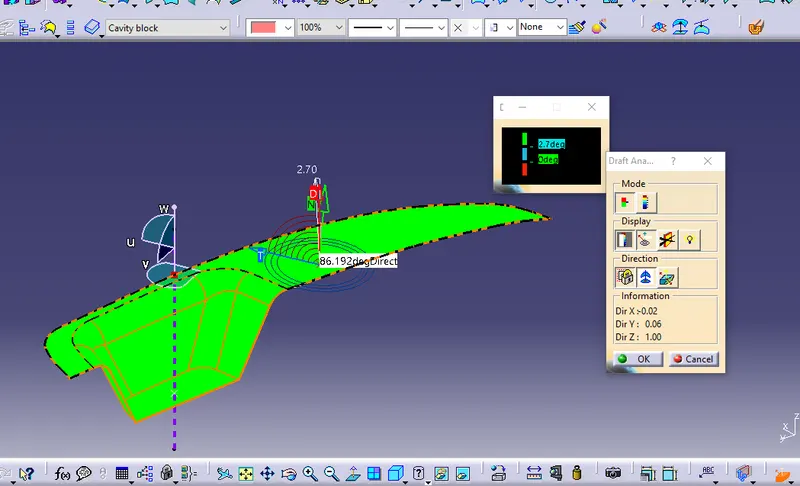
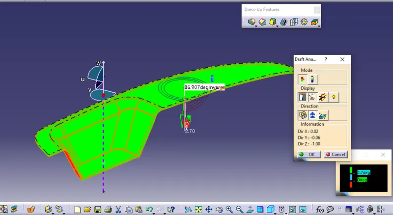
First the class A surface is checked before creating the class-B&C surface and finally the solid body must be analyzed. Both can be done by following the below procedures.by changing the view mode to custom view parameters – Material mode then the feature draft analysis is enabled.
Then the compass was activated and placed with the tooling axis by dragging the red pointer and then locked it. Then by selecting the quick analysis mode, the normal value will be 3 deg and checked for the components draft angle.
The green color area shows that it satisfies the 3 deg draft angle. If not satisfied then by using the running point tool the area is measured and then altered to get a successful draft for the created tooling direction.
Draft analysis For Class-A surface:
Draft analysis For Solid component:
Core and Cavity:
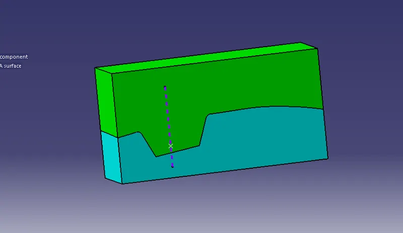
A core is the one part of the mold and it is responsible for half of the molded part, actually core is the projection of body and Cavity is the depression of the body. These core and cavity combine to form a mold. Then the plastic material is injected into this mold to get the plastic part.
Parting surface:
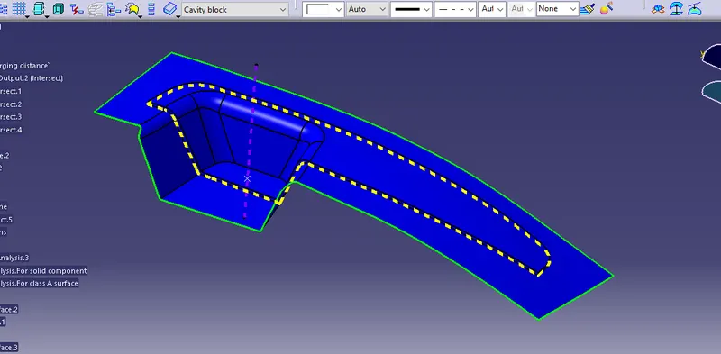
Injection mol has two major components one is core another is cavity. During the injection molding process, the two halves are pressed tightly from a sealed hollow to avoid the melt flow leakage and maintain certain holding pressure, The pressed surface are called parting surface, usually parting surface are biggest projection outline of the part.
Parting Line:
It is the area in which parting surface and component meets or it is junction between core and cavity. And the parting surface has some set of rules because the product quality mostly depends on the parting surface.
Principles to design parting surface
- Design the injection mold simple as possible, Avoid the side parting as much as possible to reduce complexity of the mold making.
- Ease of De-molding as far as possible, for instance the plastic parts should stay in fixed half of injection mold and should ejected by ejection system avoiding side De-molding action,
- Ensure the dimension accuracy of the molded parts, try to make the parts similar dimension accuracy requirements in same mold to reduce manufacturing and assembly errors.
- Ensure appearance requirement of molded parts, Finish or mismatch usually occurs on parting surface, So the parting surface should not be designed on high quality requirement surfaces.
- Ensure adequate venting, if possible, parting surface should be place at the end of the mold flow. This is going to be advantage of filling and venting.
Core design:
To extrapolate Class-A surface
Trim class-A with class-C to get inside portion
Now, Trim the B surface with the output of Class A & C that will be parting surface with respect to area. Extrude the sketch overall through the tooling direction are trim it with parting surface
Part body of core
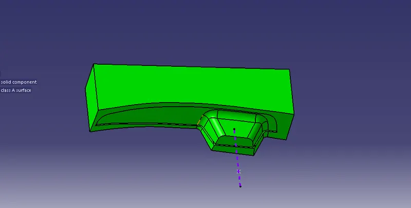
Similarly, Repeating the same as done for the cavity part and trim it on other side surface
Part body of cavity
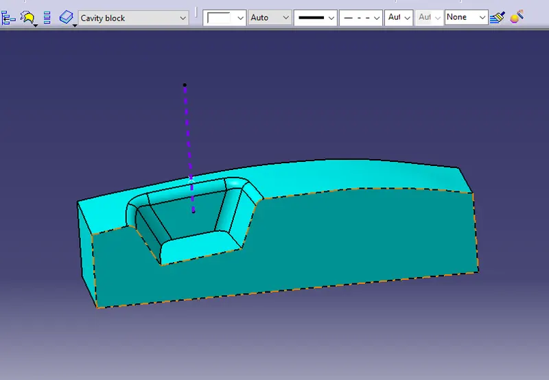
The core & Cavity are Translated to the certain value for understanding.
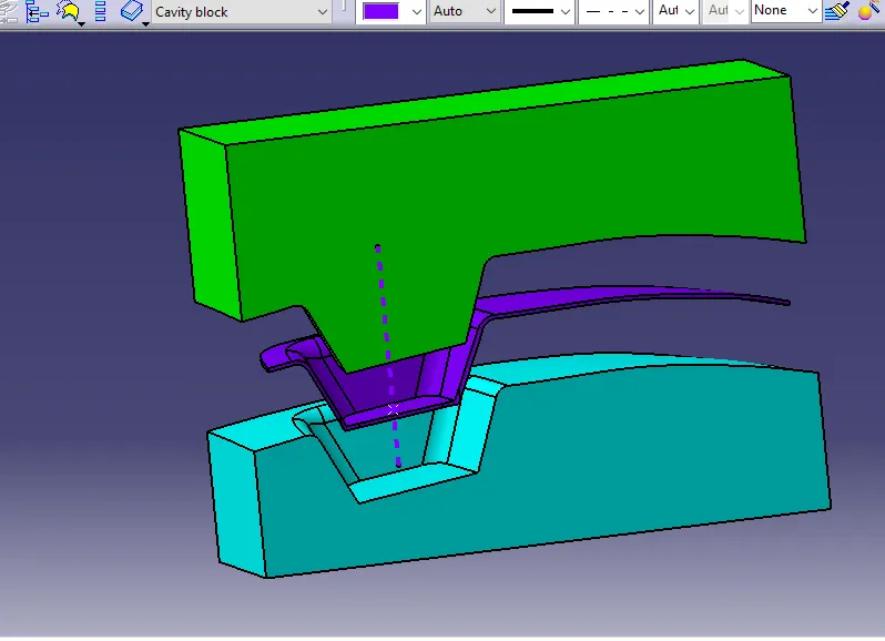
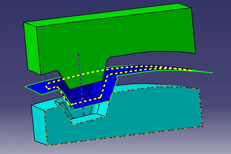
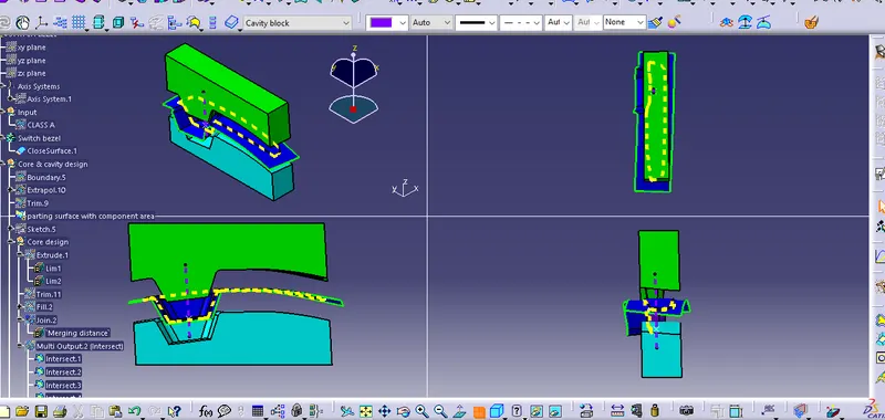
Isometric view:
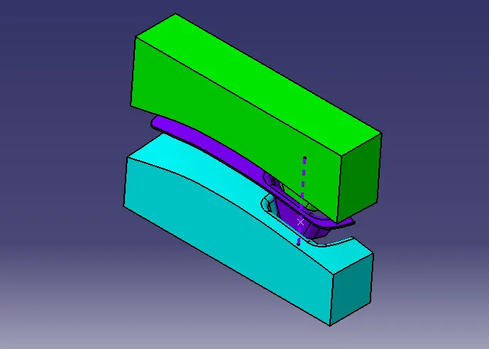
Front view:
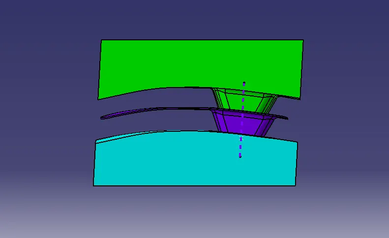
side view:
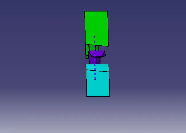
Top view:
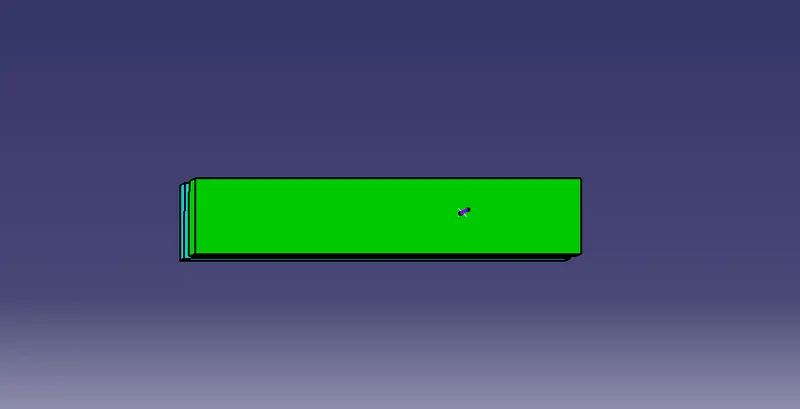
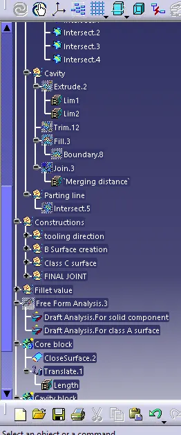
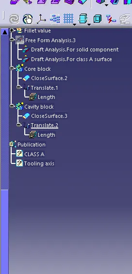
Tree structure:
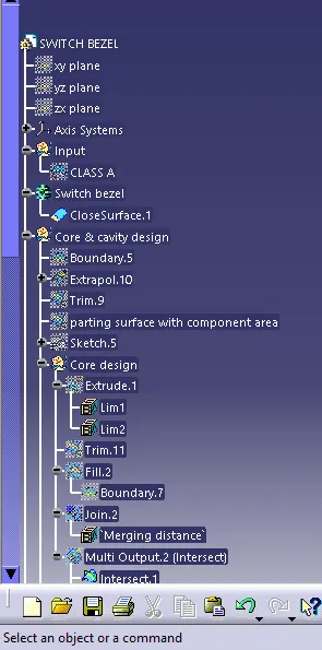
Result:
The core and cavity for the switch bezel has been created as per the design rules.