Week 8 - Challenge 5 - Core & Cavity Design
CORE AND CAVITY DESIGN FOR SWITCH BEZEL COMPONENT:
OBJECTIVE:
To create a core and cavity for the switch bezel component.
DRAFT ANALYSIS:
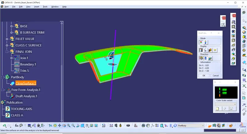
Draft analysis was done on the switch bezel component to ensure the proper tooling direction.
CORE:
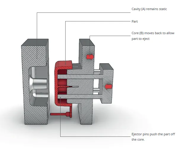
The upper half of the mold is called core. It is the side of the tool where plastic part is injected from. Also known as the male part which forms internal shape of the plastic component.
CAVITY:
Bottom half of the mold is called cavity. Cavity forms void inside the mold that the molten plastic fills. Also known as female part which forms the external shape of the plastic component.
CORE DESIGN:
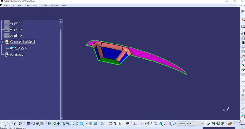
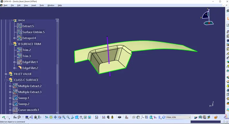
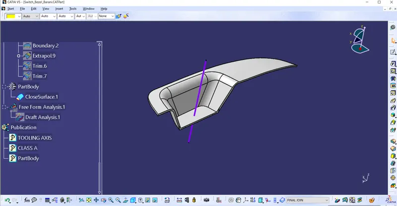
Here I have designed the core for the switch bezel component(Shown in the figure). Switch bezel component is developed into part body from class A surface by creating class B and class C surface.
Class B Surface:
Class C surface:
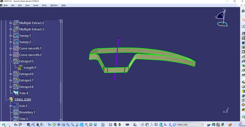
Closed part body:
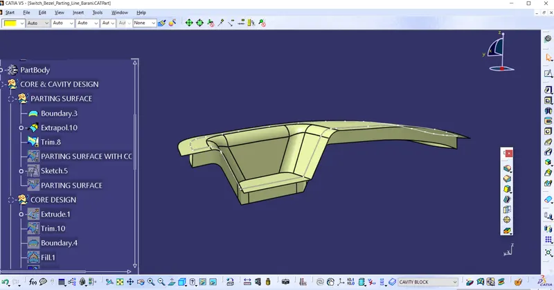
Parting Surface:
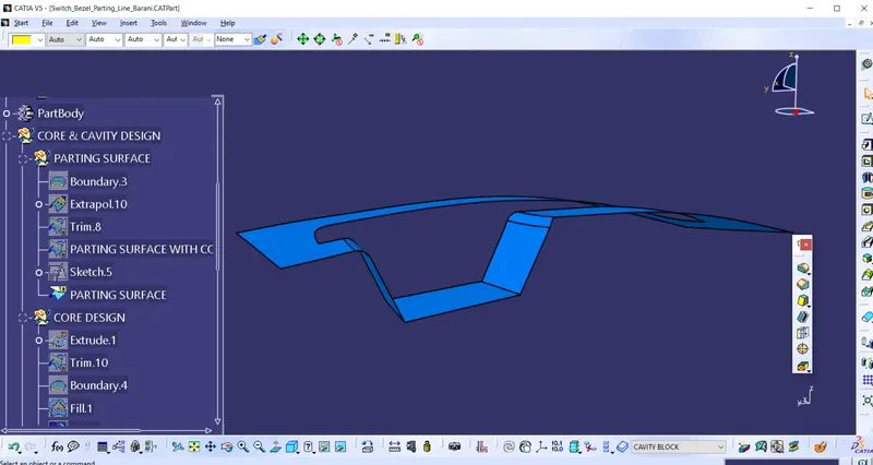
Class A surface is extrapolated by creating boundary around it. This surface is trimmed with class C and again trimmed with class B surface. This surface is known as the parting surface. The surface which seperates or inbetween core and cavity is called parting surface.
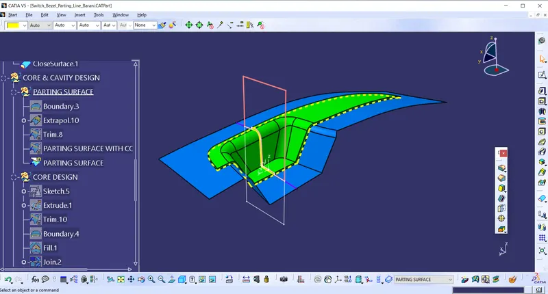
Parting line:
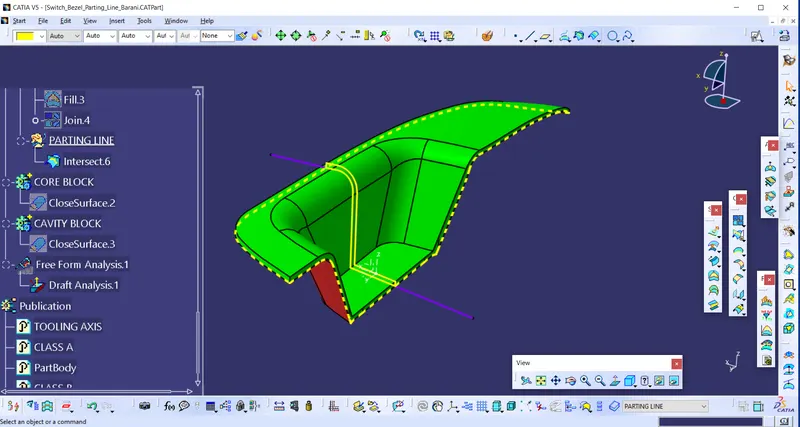
The intersection of parting surface and class b is known as the parting line as highlighed in yellow colour in the following figure.
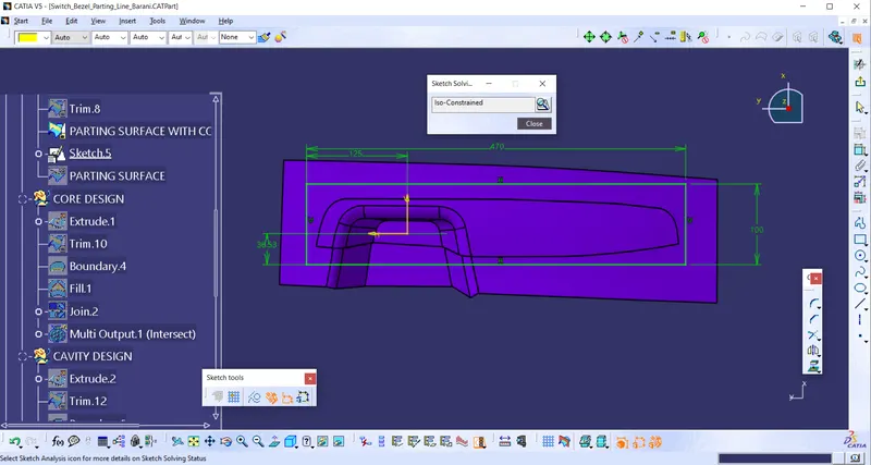
Over the parting surface created arectangle and extruded it as shown in the figure.
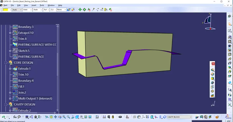
This extrude is trimmed with parting surface and filled the open side with fill command by creating a boundary in it.
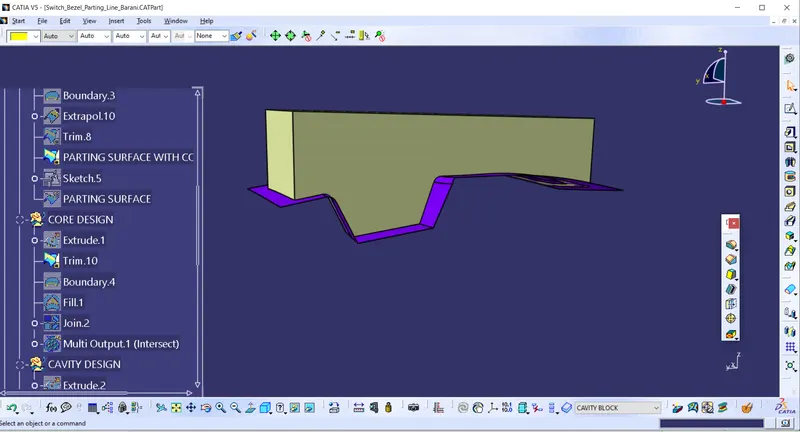
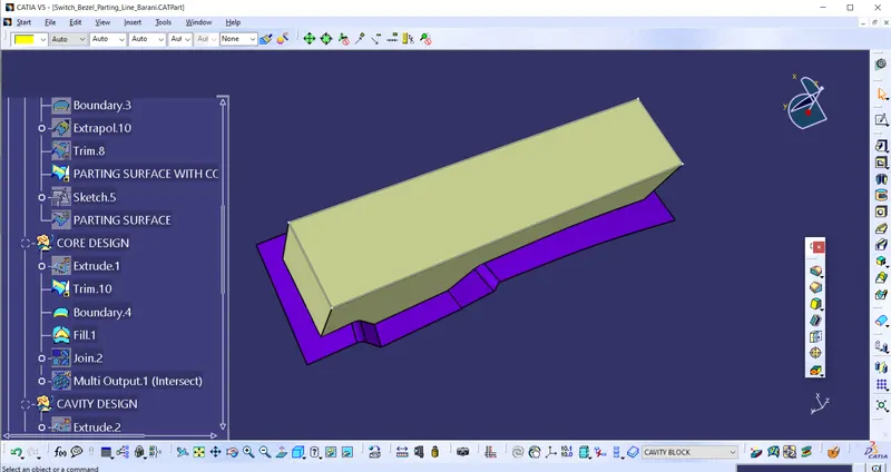
Closed surface is converted into part body in the part workbench as shown in the figure.
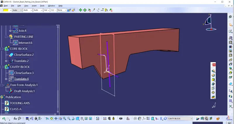
CAVITY:
Same rectangle is used to extruded in the opposite direction as shown in the figure.
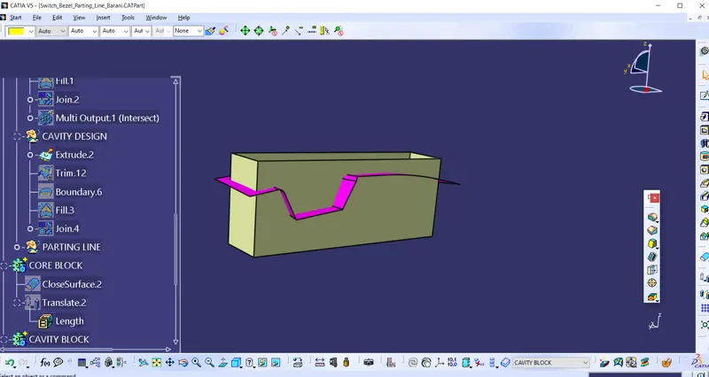
This surface is trimmed with class B surface. Open space is closed by fill command by creating boundary around it.
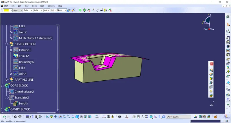
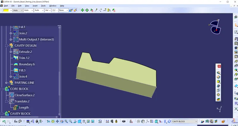
Closed surface is converted into part body in the part workbench.
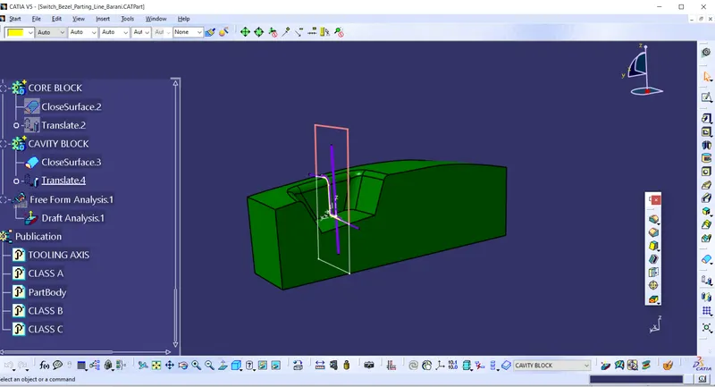
Core and cavity is assembled as shown in the below figure.
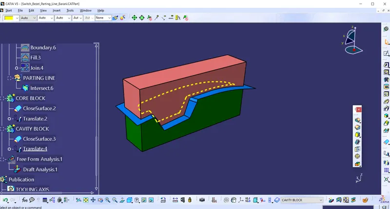
The intersection of core and cavity as follows.
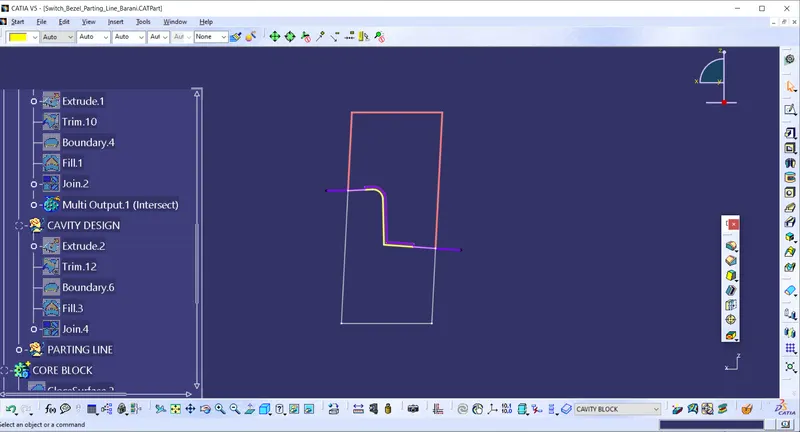
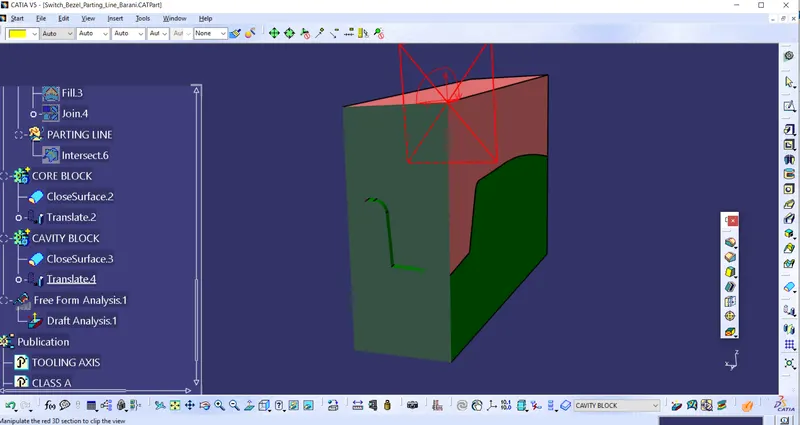
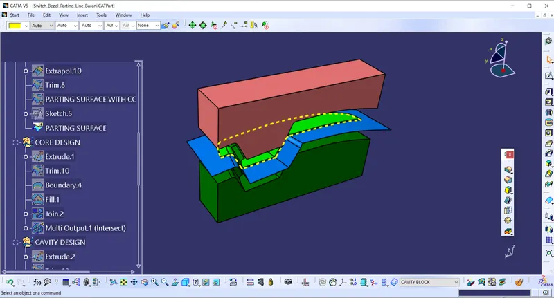
Following image shows the core,cavity,parting line and surface.
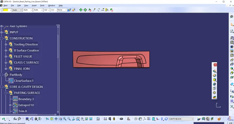
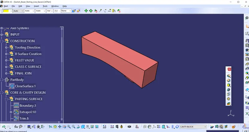
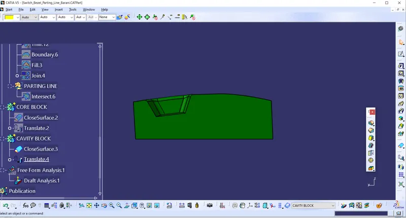
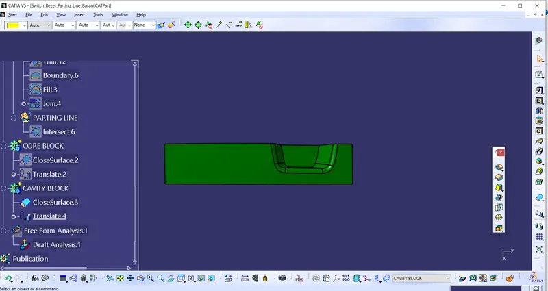
Different views of core and cavity are as follows.
CORE:
Front view:
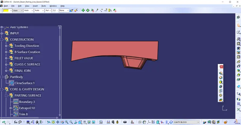
Bottom view:
Isometric view:
CAVITY:
Front view:
Top view:
Isometric view:
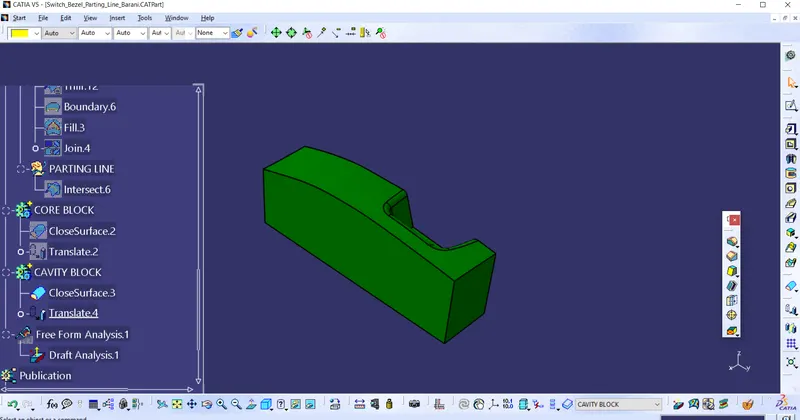
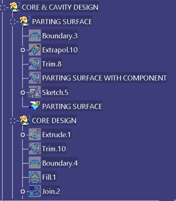
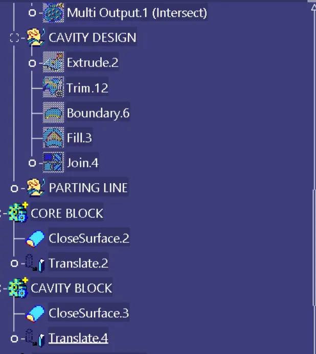
TREE STRUCTURE:
RESULT:
Core and cavity for the switch bezel component was created along with the tooling direction.