Radar Mast & Final Assembly of Yacht
DESIGN OF SUNSEEKER PREDATOR YACHT
OBJECTIVE:
To learn and understand the Surface modelling feature in Solidworks by modelling Sunseeker Predator Yacht.
INTRODUCTION:
Surface modelling is a technique for engineering freeform surfaces with a computer aided system. It is the method of showing or representing the solid objects.Solidworks surface feature allows us to create geometry that might otherwise be impossible using standard extrude boss/base, sweeps, revloves and lofts. It also let us to create complex geometries and shapes, make edits to existing models and repair imported parts.
DESIGN METHODOLGY:
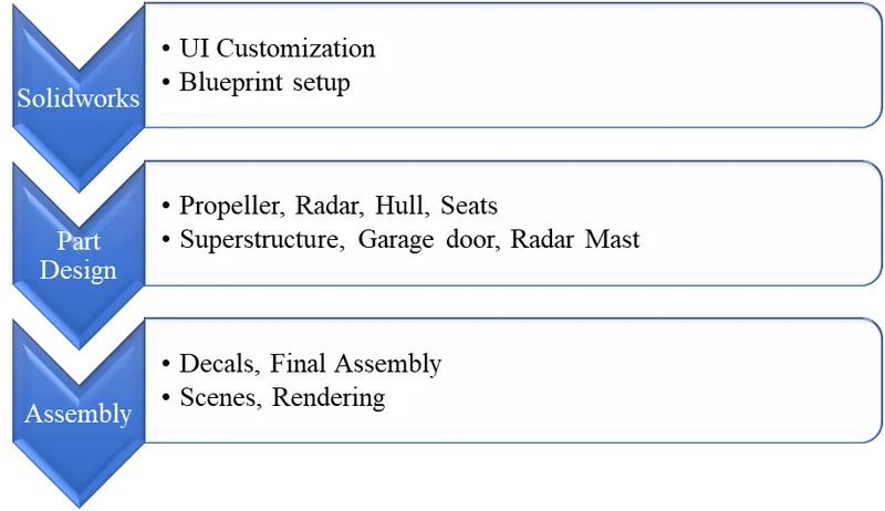
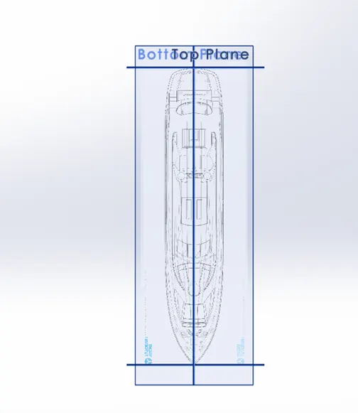
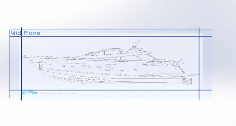
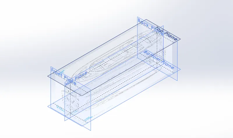
Customized the user interface for ease of access to design the Sunseeker Predator Yacht. Then setup a blueprint of yacht in front, back, top, bottom and side planes and rename those accordingly. Design all the parts with the base of blueprint and save separately. Add decals whenever required and all the parts are assembled. Specific scenes are added to the background. Lights and cameras are added for good output. Finally rendering was done in Photo view 360.
DESCRIPTION:
Blueprint setup:
Blueprint is nothing but sketch picture of Sunseeker. Here blueprints are used like drawing. All sketches are added to the planes and renamed accordingly. Followings are the images after blueprint setup.
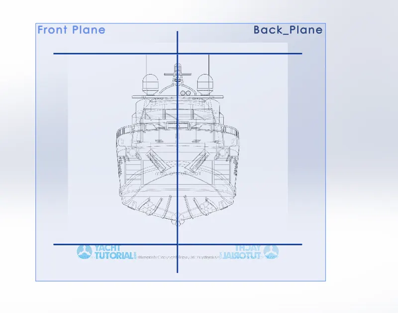
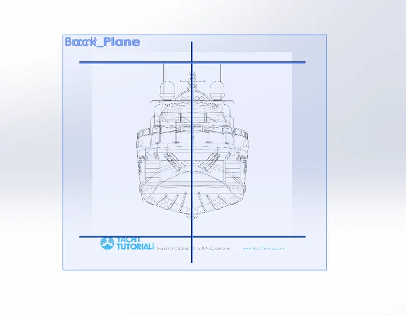
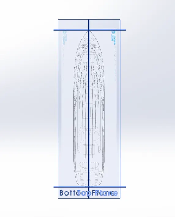
The Sunseeker Predator yacht has the following parts.
- Propeller
- Radar
- Hull
- Garage door
- Seats
- Superstructure
- Radar Mast
Geometric constraints:
It is a constraint that define geometric relationships between two geometric elements. For example two lines may be defined as parallel, equal or collinear. Likewise geometric constraints are used throughout the sketching processes. Followings are geometric constraints.
- Coincident - It Defines a coincident geometric constraint to two points on entities.
- Fix - It is used to fix two entities.
- Perpendicular - It is used to make two lines perpendicular between them.
- Parallel - It is used to define two lines parallel.
- Horizontal - It defines pairs of points or two lines on entities to be parallel to the X-axis of the current coordinate system.
- Vertical - It defines pairs of points or two lines on entities to be parallel to the Y-axis of the current coordinate system.
- Tangent - It is used to make two entities tangent with each other.
- Collinear - It defines lines to be collinear.
Procedure and features used to design the parts are as follows.
1.Propeller:
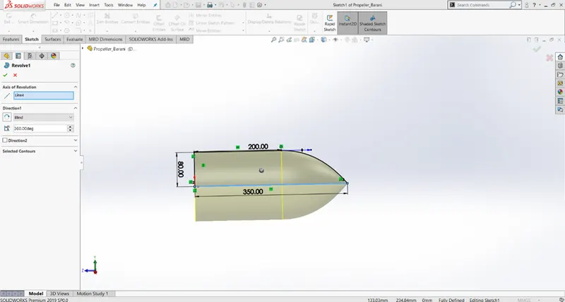
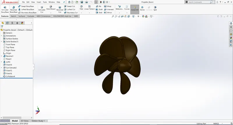
A device that consisting of central hub with rotating blades placed and twisted so that each forms part of a helical surface and that is used to propel a yacht. Propeller is drawn by using the blueprint of yacht.
Sketch entities:
- Line - Used to create a line.
- Spline - Used to sketch a spline. With the use of spline we get a curved structure.
- Circle - Used to sketch a circle.
- Rectangle – Used to create a rectangle.
Features:
1.Revolved boss/base - Creates a solid feature around an axis as in the figure. The revolve is shown in the figure.
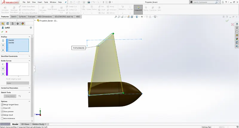
2. Loft Boss/Base - Used to create solid feature between two or more profiles as shown in figure.
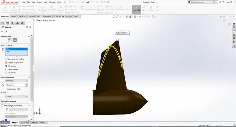
3.Fillet - Used to create rounded internal/external face along with one or more edges. Fillet is shown in figure.
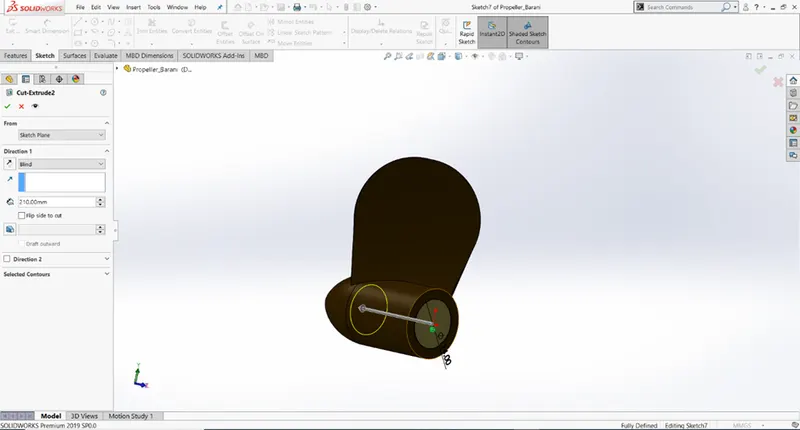
4.Extruded cut - Used to cut a solid model by extruding a sketched profile like as follows.
5.Circular pattern – Used to create a pattern in circular direction.
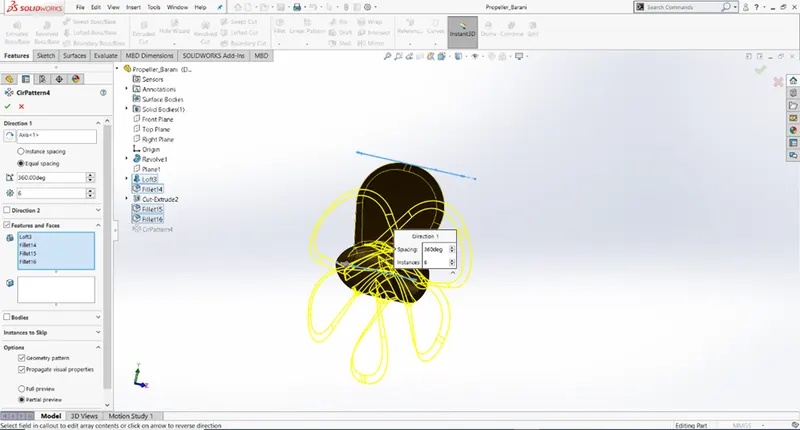
Look at the Propeller.
2.Radar:
A radar device acts as major navigation for boaters. It helps in detecting boats, birds, landmasses and weather system.
Sketch entities:
1. Line
2. Polygon - Used to to create a polygon.
3. Circle.
Sketch tools:
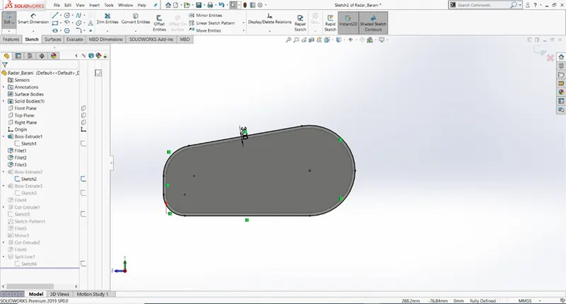
1.Offset- Used to offset curves, lines with a specified distance.
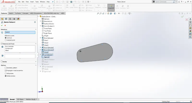
2.Sketch pattern – used to create pattern in circular direction.
Features:
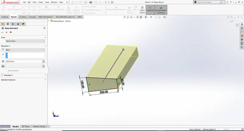
1.Extruded boss/base - used to create a solid feature as shown in figure.
2.Fillet
3.Extruded cut
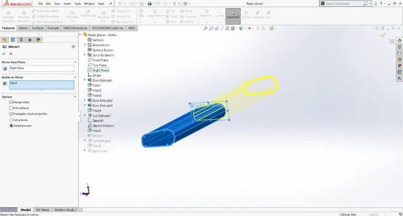
4.Mirror- Used to mirror bodies about face or a plane as in the below figure.
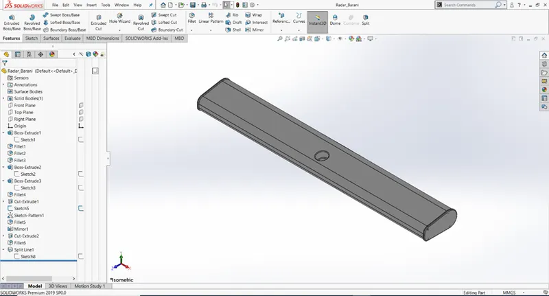
Radar is designed as shown in the figure.
3.Hull
A body of boat is called its hull. It is also watertight body. The hull may open at the top or it may be fully or partially covered with a deck. In this case it’s covered with deck for Superstructure.
Sketch entities:
1.Line
2.Spline
3.Circle
4.Ellipse – Used to create an ellipse sketch
5.Straight slots
Sketch tools:
1.Offset
2.Trim
3.Fillet
4.Linear pattern
5.Convert entities - Used to convert model edges or sketches into sketch segment.
Features:
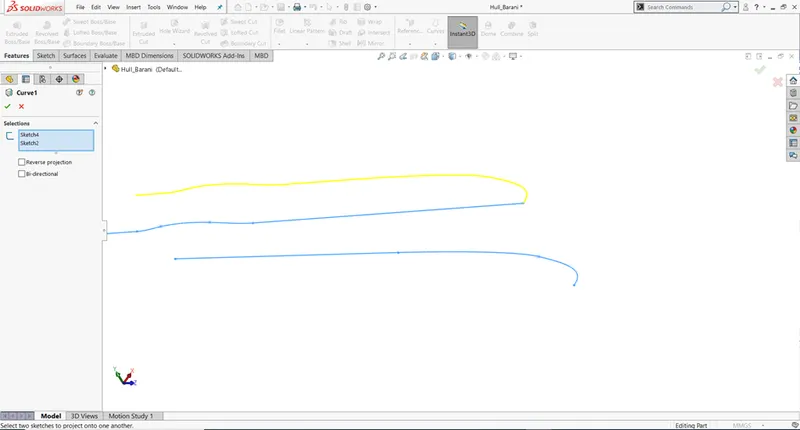
1.Projected curve – Used create a curve of a projected intersecting surface of two curves.
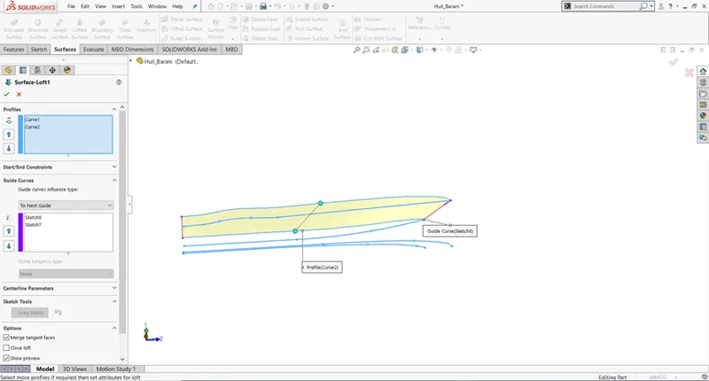
2.Lofted Surface – Used to create a lofted surface between two or more profiles as shown in the figure.
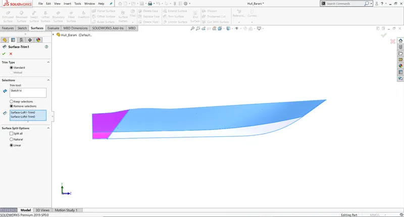
3.Surface Trim – Trims a surface where one surface intersects with another surface or plane or sketch as shown in figure.
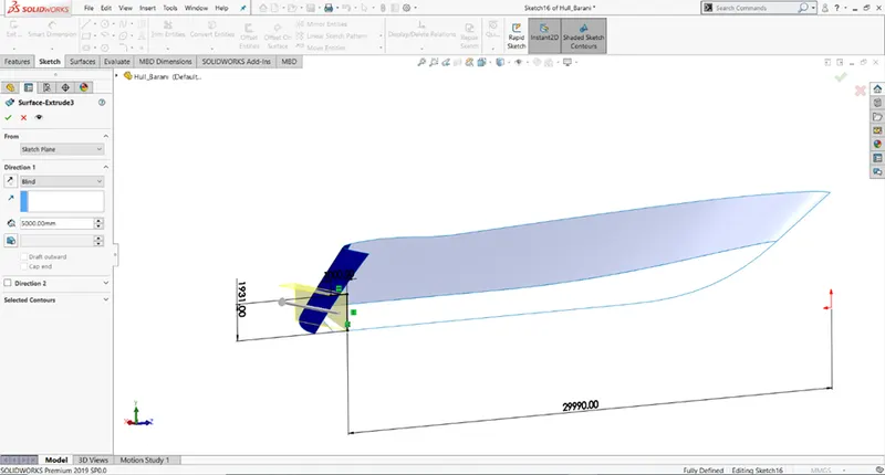
4.Surface Extrude – Used to create extruded surface as shown in the figure.
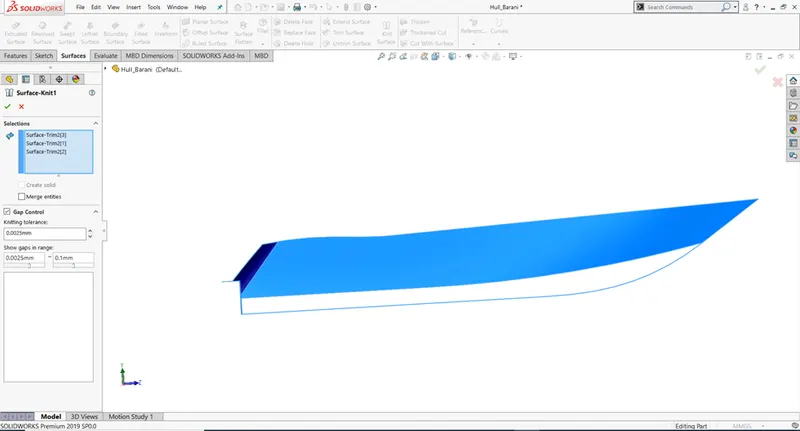
5.Surface knit – Used to combines two or more adjacent, non-intersecting surfaces together.
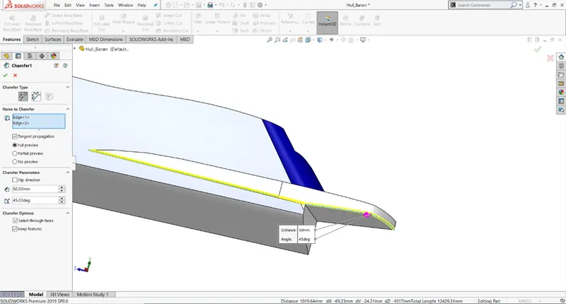
6.Chamfer - Used to create a symmetrical slopping surface at an edge or corner as shown in the figure.
7.Shell – Used to remove material from a solid body to create a thin-walled feature as shown in figure.
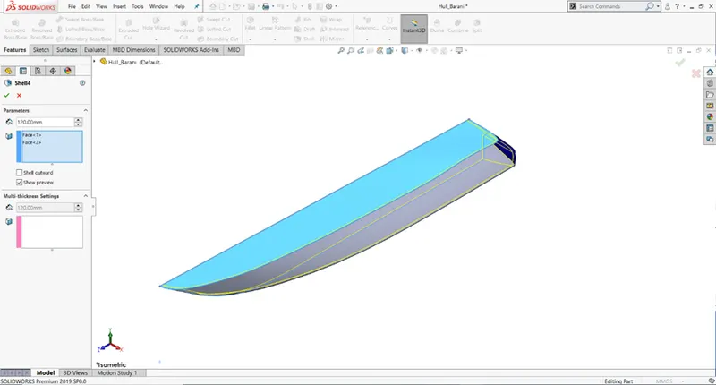
8.Extruded boss/base
9.Extruded cut
10.Fillet
11.Plane – Used to create plane as shown in the figure.
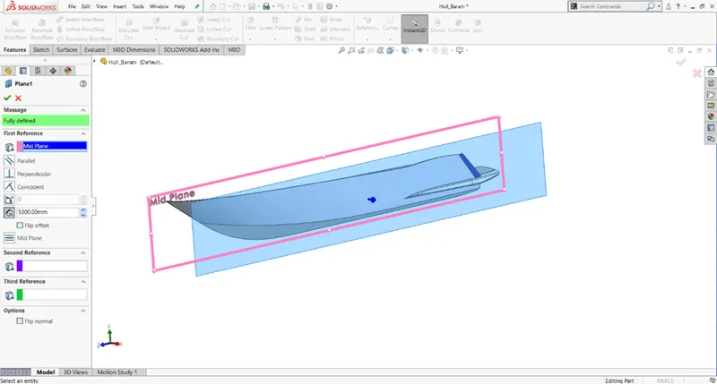
12.Swept boos/base - Used to sweep a closed profile along a open or closed path to create a solid feature as shown in the figure.
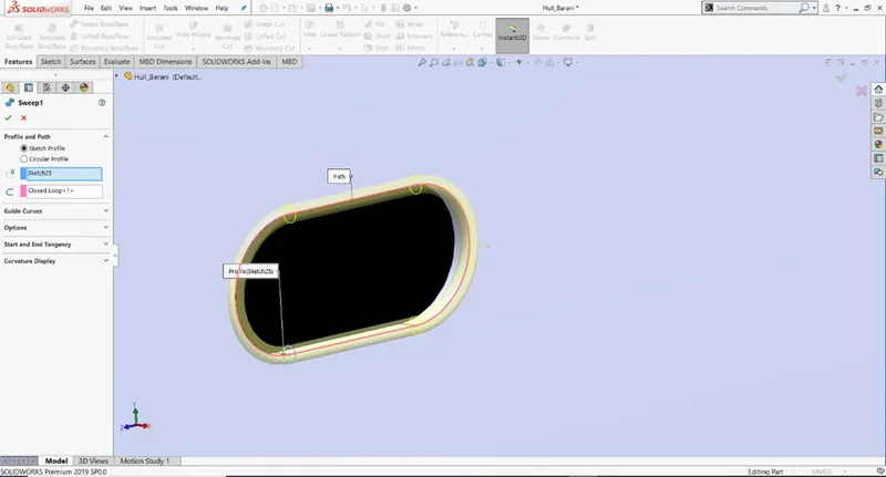
13.Revolved boss/base.
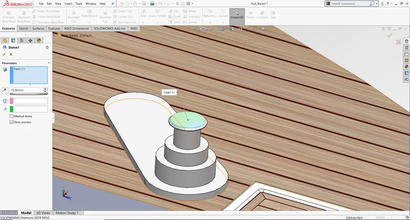
14.Dome - Used to create dome feature on a face as shown in the figure.
15.Helix/Spiral – Used to create spiral curve as shown in figure.
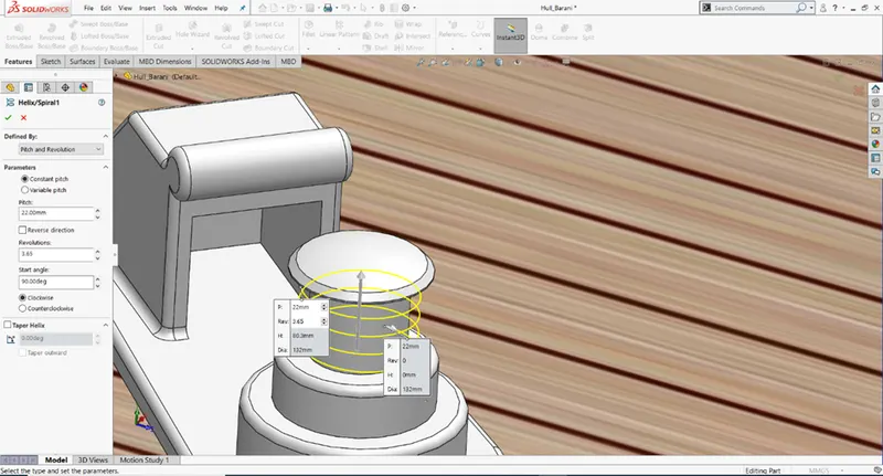
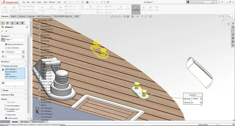
16.Linear pattern – Used to create patterns of features, faces and bodies in linear direction.
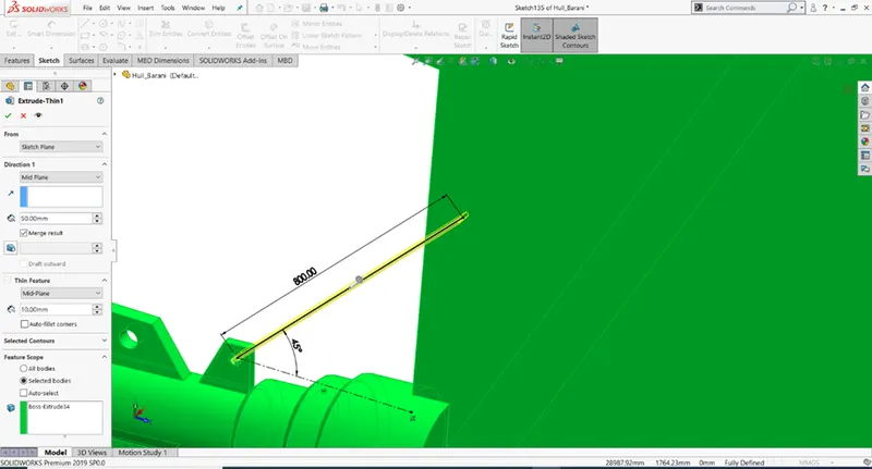
17.Thin extrude – Used to create a thin extrude as shown in figure.
18.Mirror
19.Combine – Used to combine two or more solid bodies.
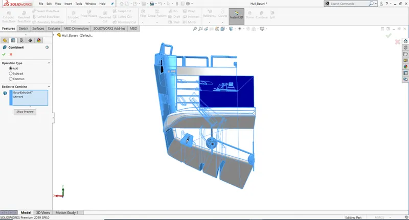
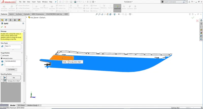
20.Split – Used to create multiple bodies from a single body or separate part from a existing body as shown in figure.
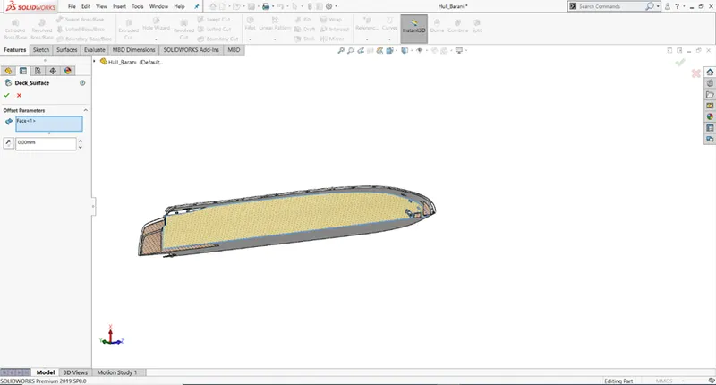
21.Surface offset – Used to create an offset surface as shown in figure. It’s renamed as deck surface. It is later used as reference for Superstructure part.
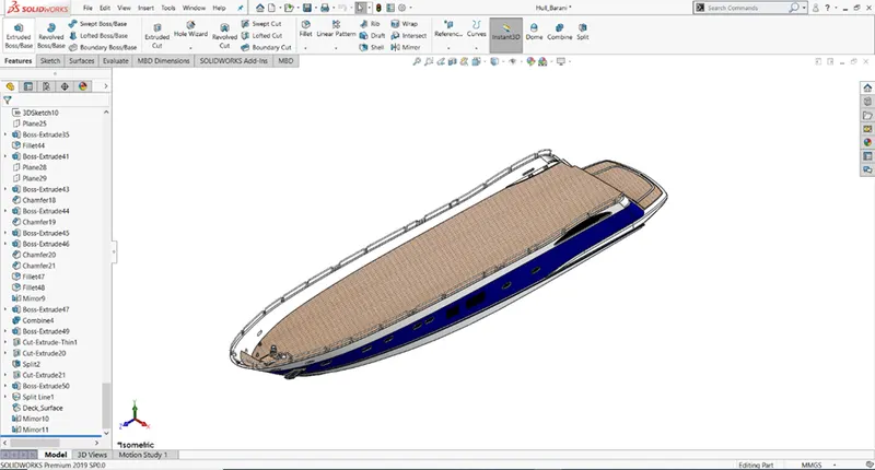
Colours and decals are added as shown in the figure.
4.Garage door:
Sketch entities:
1.Line
2.Circle
Features:
1.Extruded cut
2.Shell
3.Fillet
4.Mirror
5.Plane
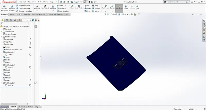
The garage door as shown in the figure.
5.Seats:
There are three seats are designed in the yacht, front, middle and rear seats.
1.Front seat:
Sketch entities:
1.Spline
2.Line
Sketch tools:
1.Offset
2.Convert entities
Features:
1.Surface swept – Used to create a surface feature by sweeping an open or closed profile along on open or closed path as shown in figure.
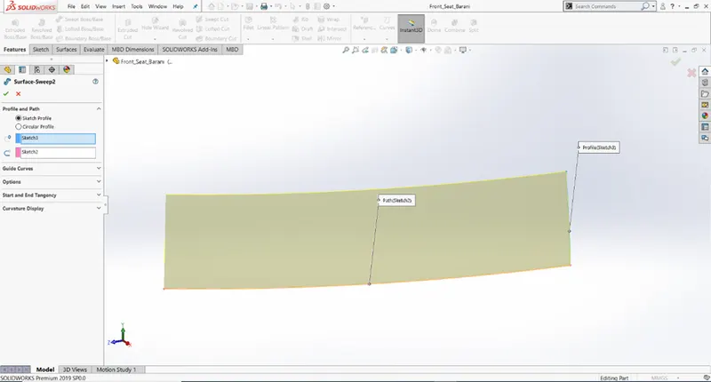
2.Extruded surface.
3.Trim surface.
4.Filled surface – Used to construct a surface patch within a boundary defined by existing model edges, sketches or curves as shown in the figure.
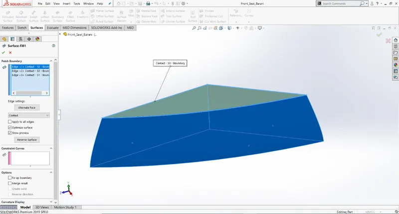
5.Lofted surface.
6.Knit surface.
7.Chamfer.
8.Revolved boss/base
9.Extruded cut.
10.Fillet.
11.Mirror.
12.Dome.
Front seat as shown in the following figure after addition of colours.
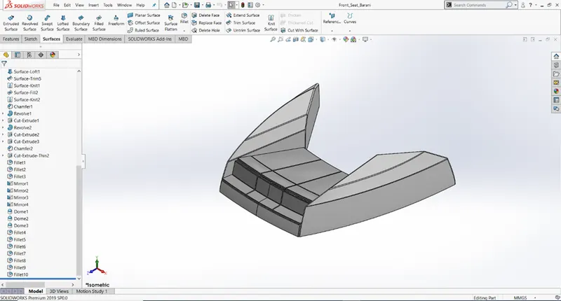
2.Middle seat:
Sketch entities:
1.Line.
Sketch tools:
1.Offset.
2.Trim.
Features:
1.Extruded boss/base.
2.Plane.
3.Chamfer.
4.Fillet.
5.Mirror.
6.Extruded cut.
Middle seat as shown in the below figure.
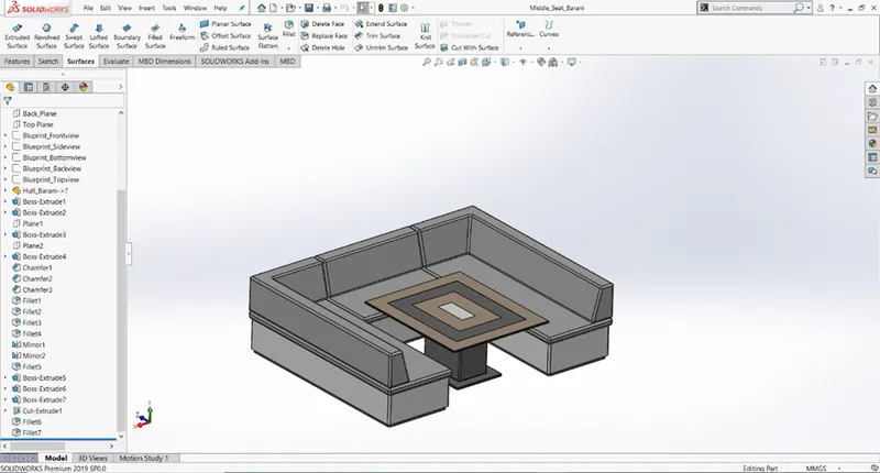
3.Rear seat:
Sketch entities:
1.line.
2.Spline.
3.Circle.
4.Rectangle.
5.Fillet.
Sketch tools:
1.Convert entities.
2.Offset.
3.Trim.
Features:
1.Swept surface.
2.Offset surface.
3.Trim surface.
4.Knit surface.
5.Extruded surface.
6.Lofted surface.
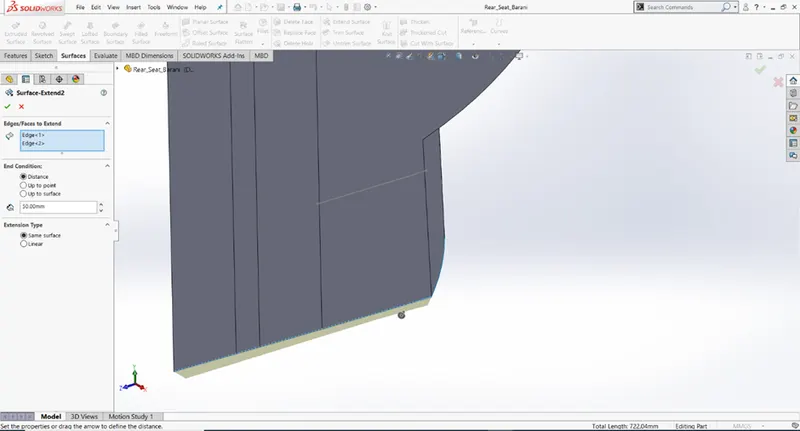
7.Surface extend – Used to extend edge of the surface as shown in the figure.
8.Extruded boss/base.
9.Extruded cut.
10.Chamfer.
11.Plane.
12.Fillet.
13.Swept boss/base.
14.Mirror.
15.Revolved boss/base.
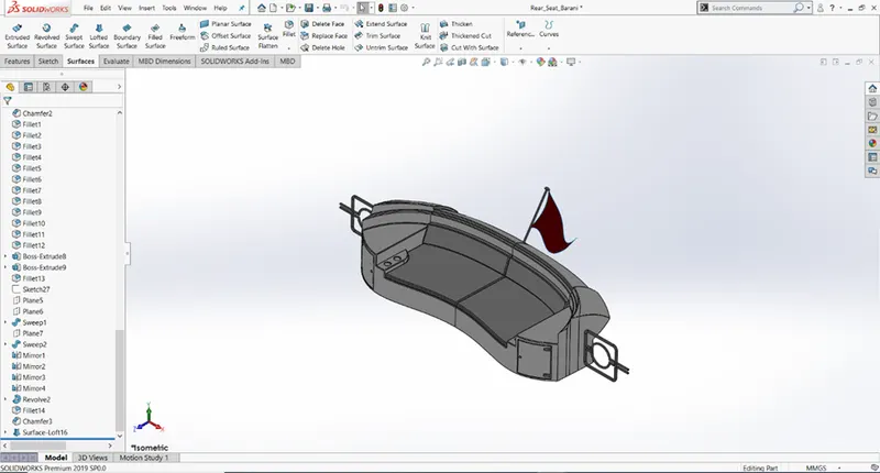
Rear seat shown in following figure.
5.Superstructure:
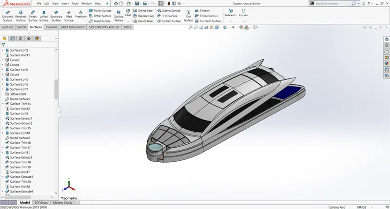
Superstructure is an extended construction of any building or platform that rises above the rest of the building or platform in a distinct manner. It simply means to add a construction to an already existing structure. Here it is the part of the sunseeker that emerges from the deck.
Sketch entities:
1.Spline.
2.Line.
3.3D sketch line.
4.Circle.
5.3 point corner rectangle.
6.Centrepoint arc.
7.Rectangle.
Sketch tools:
1.Covert entities.
2.Trim.
3.Offset.
4.Split entities – Used to split the entities.
Features:
1.Extruded surface.
2.Plane.
2.Swept surface.
3.Knit surface.
4.Fillet.
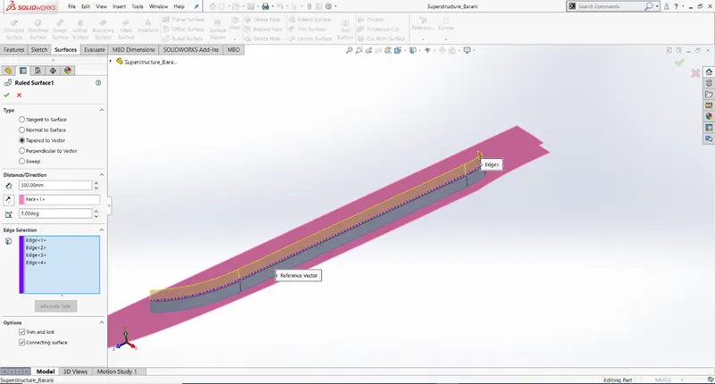
5.Ruled surface – Used to inserts ruled surfaces from edges as shown in the figure.
6.Trim surface.
7.Projected curve.
8.Lofted surface.
9.Filled surface.
10.Extended surface.
11.Extruded boss/base.
12.Extruded cut.
13.Fillet.
14.Offset surface.
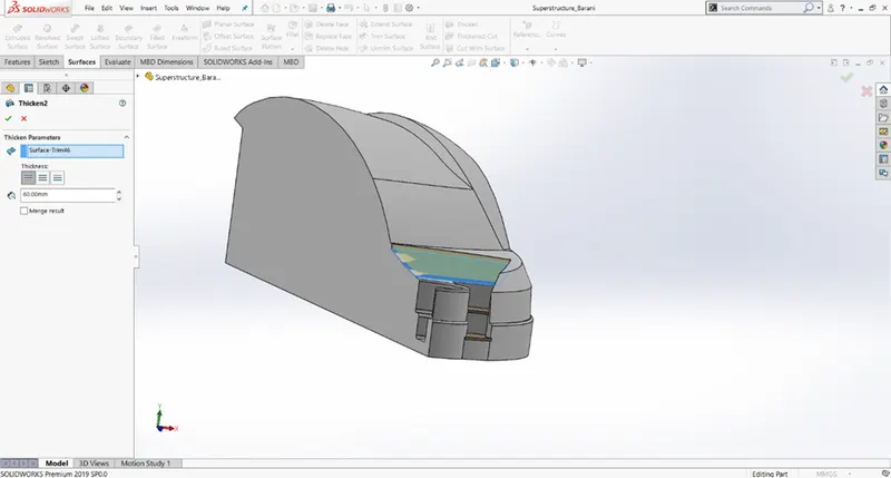
15.Thicken – Used to create a solid feature by thickening one or more adjacent surfaces as shown in the figure.
16.Dome.
17.Swept base/boss
18.Mirror.
19.Chamfer.
Superstructure is shown in the below figure.
6.Radar mast:
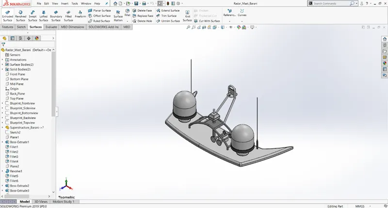
It is used to detect other ships and land obstacles, to provide bearing and distance for collision avoidance and navigation at sea.
Sketch entities:
1.Line.
2.Spline.
3.3 point arc.
4.Circle
5.Rectangle.
Sketch tools:
1.Trim.
2.Offset.
Features:
1.Extrude boss/base.
2.Fillet.
3.Plane.
4.Revolved boss/base.
5.Swept boss/base.
6.Mirror.
7.Projected curve.
8.Chamfer.
9.Dome.
10.Shell.
Radar mast is shown in the below figure.
ASSEMBLY OF YACHT:
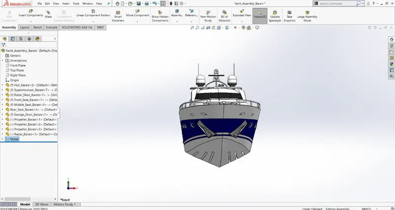
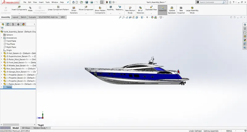
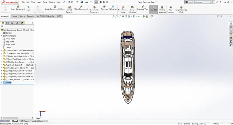
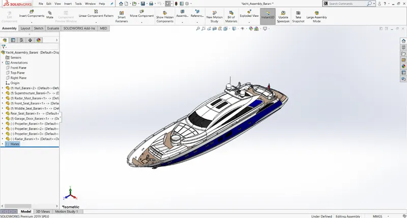
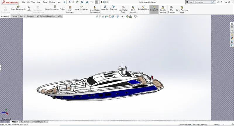
It is important to assemble the yacht after creating all parts separately. Assembly is done by using assembly option in Solidworks. Then have to insert all the parts one by one. In this case first Hull is inserted followed by Superstructure, Radar mast, Front seat and Middle seat. These parts will fix automatically because it’s created respective planes. Rear seat is inserted and given coincident mate option followed by distance to fix it in the right position. Next garage door is inserted and fixed with concentric mate. Then propeller is inserted and fixed with another concentric and distance mate options. This step is repeated to fix 3 propellers. Finally Radar is inserted and fixed with concentric mate.
Following mates are used while assembling the yacht.
1.Coincident.
2.Concentric.
3.Distance.
Assembled images of Yacht are as follows.
RENDERING:
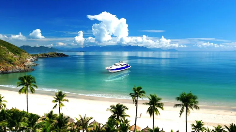
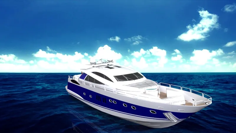
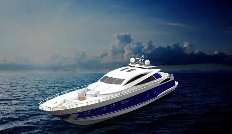
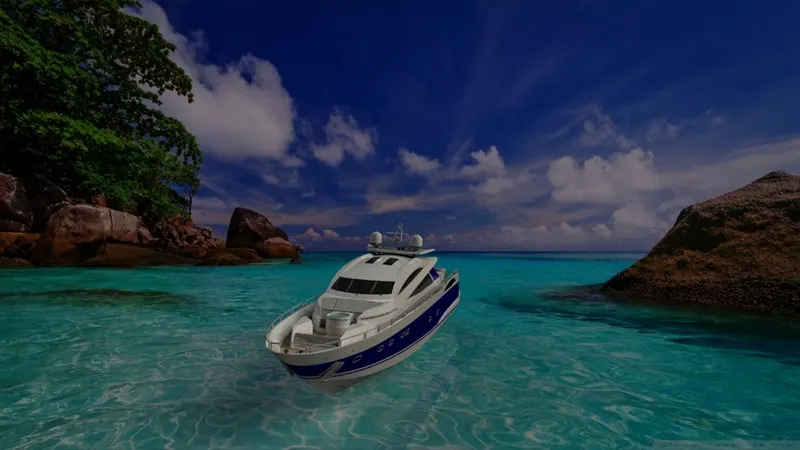
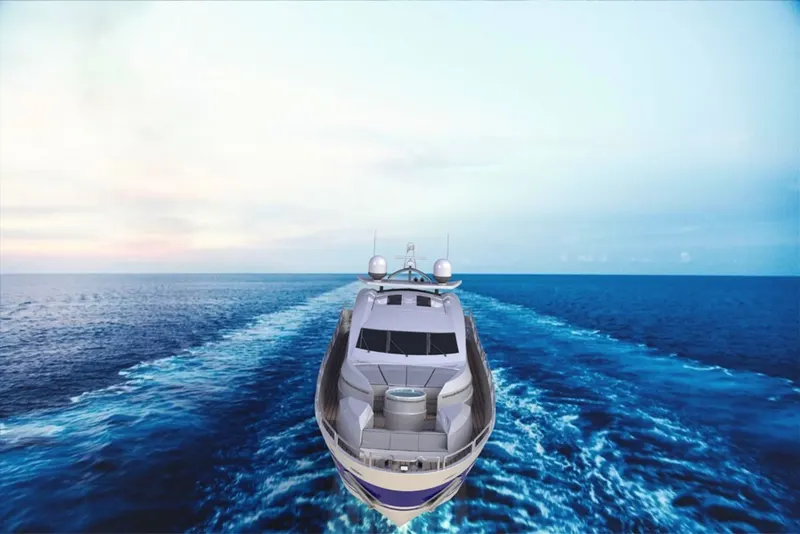
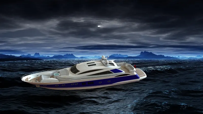
Presentation of model is important as much as designing. So model is to be rendered for better looking. In solidworks photo view 360 is used for photo realistic rendering of designed parts. It is necessary to setup a camera before rendering of the assembly. Camera view gives better perception. Here I have added 3 different camera views for rendering.
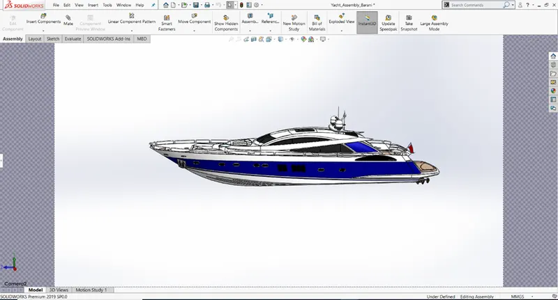
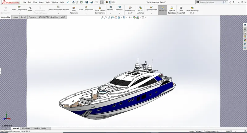
Solidworks doesn’t have the pre-loaded background scenes for boats. Because ships and boats with sea background will gives us more realistic image. So, I have added some background scenes in order to create a render. Rendered images are as follows.
CONCLUSION:
Surface modelling feature has been understood and learnt by designing sunseeker predator yacht.