Week 8 - Challenge 3 - Switch Bezel Design
OBJECTIVE:
To create the Switch Bezel Plastic component from a given Class-A surface and to create tooling axis for the same in order to perform the Draft analysis on the model.
SWITCH BEZEL:
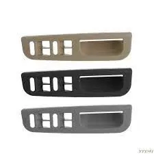
Switch bezel is a plastic component fitted in automobile doors. It has opening switches for window glass. Switch bezel is shown in the figure.

CLASS A SURFACE:
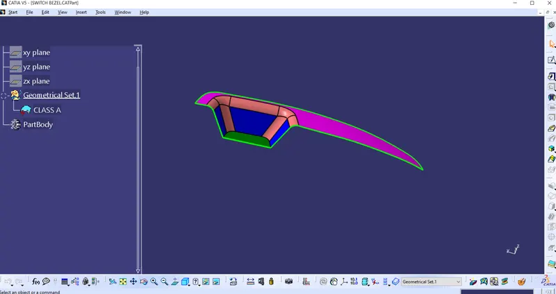
Class A surface is the pre developed surface of the component. Class A Surface is taken for Switch bezel is shown in the following figure.
TOOLING AXIS:
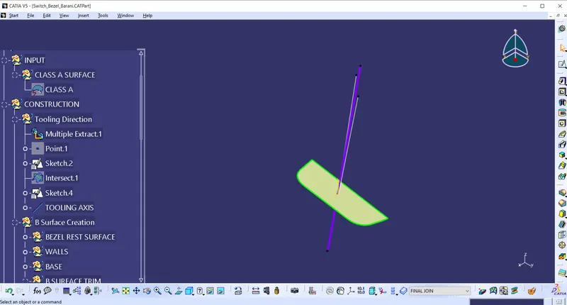
Tooling axis is very important for draft analysis. It is created by using the sides of the wall as shown in the figure. Tooling axis is highlighted in violet colour.
CLASS B SURFACE:
Class B surface is created with the reference of Class A surface. It has the thickness of 2.5 mm. First bezel rest is created with the help of extract and untrim command as shown in the figure.
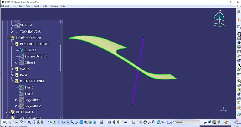
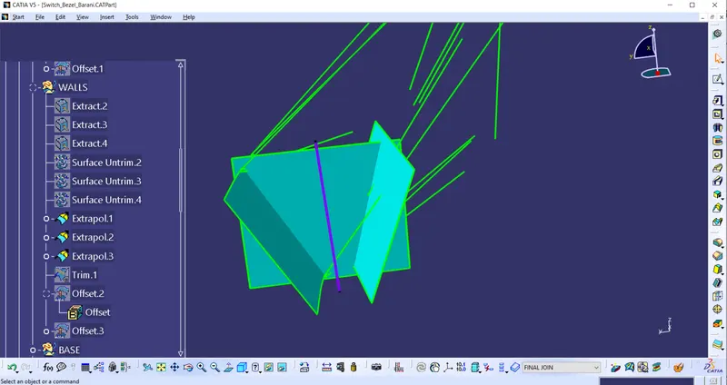
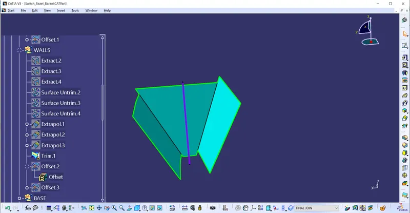
Then walls are extracted seperately and then untrimmed. Walls are extrapolated with 50 mm. Finally all walls are coincided so it is trimmed as shown in the figure.
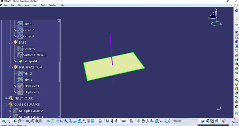
In same way base also created as shown in the figure.
Rest surface,Walls and base are trimmed together to create a B Surface.
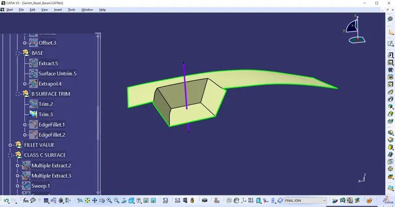
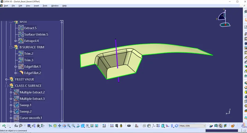
Then edges are filleted as shown in the figure.
CLASS C SURFACE:
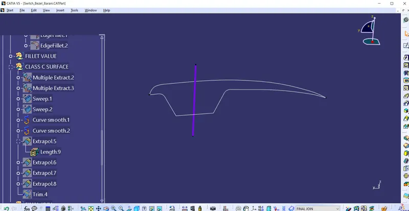
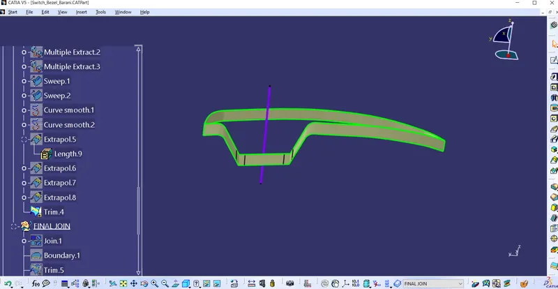
For Class C Surface Edges of class A surface is Extracted. But it has multiple points. So it is changed into smooth curve in order to reduce multiple points.
CLOSED SURFACE:
After creating class B and class C surfaces, both are joined together by using Join command as shown in the figure.
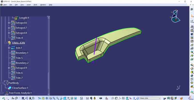
Class B and class c surfaces are trimmed with class A surface as shown in the figure.
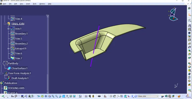
This surface is coverted into part body by using closed body command as shown in the figure.
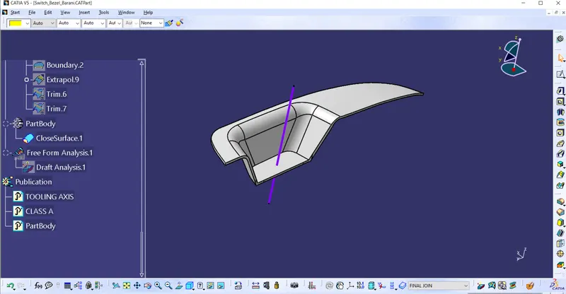
DRAFT ANALYSIS:
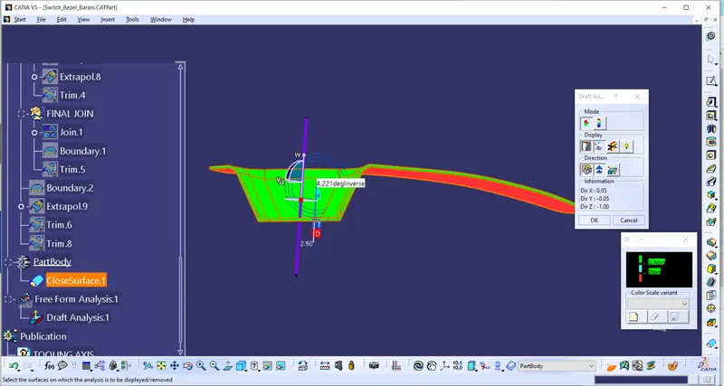
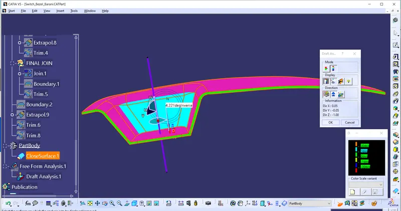
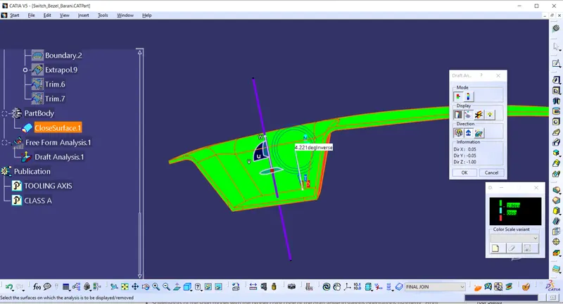
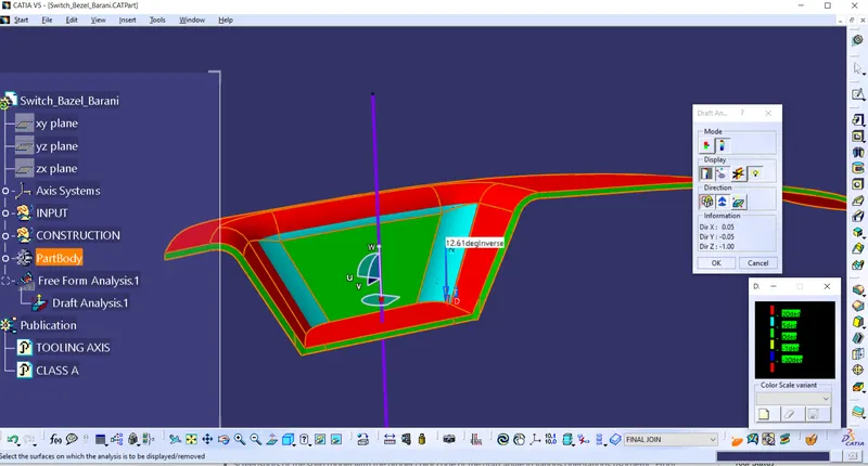
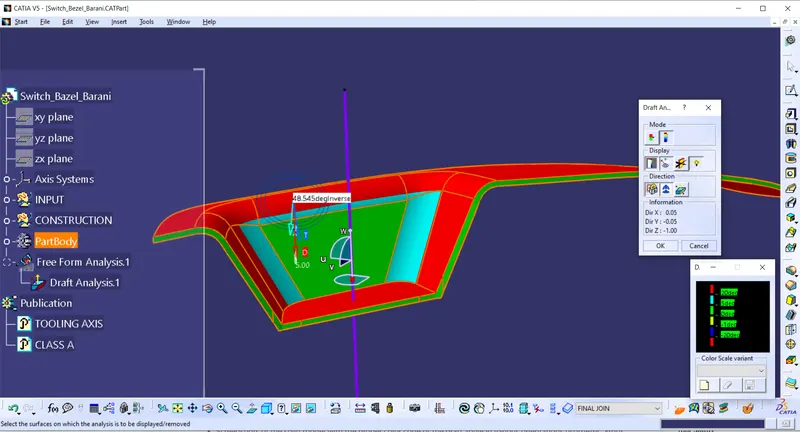
With draft analysis we can verify draft angles, examine angle changes within a face. First we have change material mode in the view mode. Then click on draft analysis option to do analysis. Located the compass on the tooling axis and I have locked the compass and inversed it to the required draft direction. In draft analysis tool we have two options one is quick analysis and the other one is Full analysis mode. Quick analysis mode has three limits positive,negative and neutral. We can change this angles and colors as per our requirement. In full analysis mode it has 5 variable limits as shown in the figure. Minimum draft angle is 3 degree. So with that reference Analysis has been done.
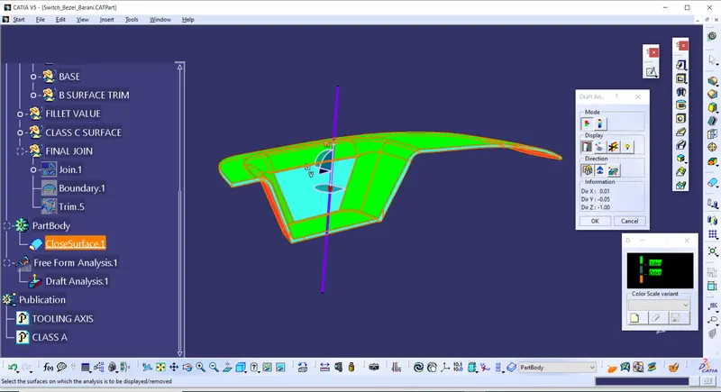
When I did quick analysis draft angle of side wall is is only 2 degree. So I have changed the angle of Tooling axis in oreder meet minimum draft angle. Following images are the draft analysis.
TREE STRUCTURE:
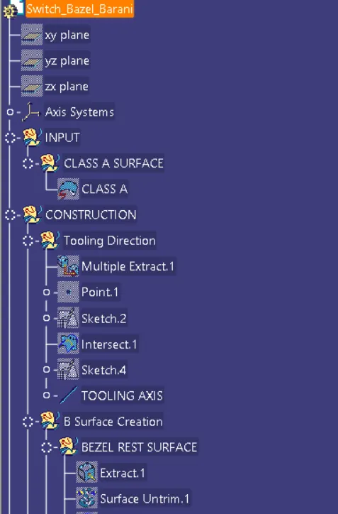
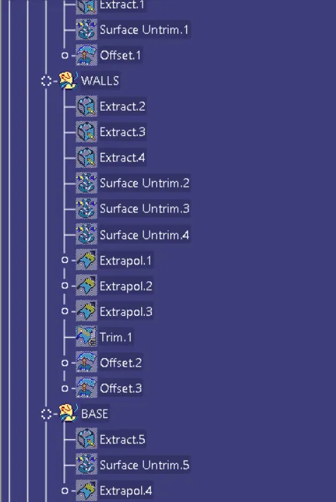
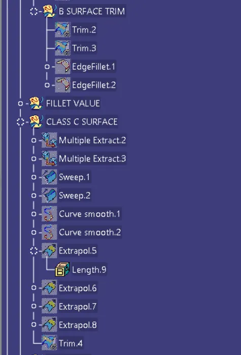
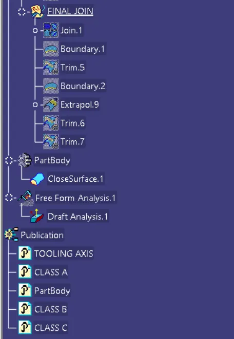
RESULT:
Switch Bezel Plastic component from a given Class-A surface is created by using class B and class C surfaces. Draft Analysis has been performed based on Tooling axis and the results are Published.