Photo Realistic Rendering
DESIGN OF AMERICAN CHOPER WITH PHOTO REALISTIC RENDERING
OBJECTIVE:
To learn and understand the basic features of Solidworks by designing American Chopper with photo realistic rendering.
INTRODUCTION:
Solidworks is a solid modelling computer aided design software which is used by many companies for designing. It lets users quickly sketch out ideas, experiment with features and dimensions and produce models and detailed drawings. AutoCAD is used for 2D drawings while Solidworks mainly created for 3D modelling. With ease of access the features Solidworks preferred in many industries.
DESIGN METHODOLOGY:
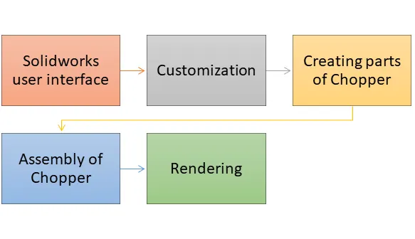
First and fore most it's necessary to know about the user interface. Solidworks user interface is very easy to understand. After I have customized as per the requirement of my design like template, short cut keys and required features. Then I have created each and every parts of American Chopper in separate part files as per the required dimensions. Next, I assembled all parts with use of mates. Then created a photo realistic rendering by using Photo view 360.
DESCRIPTION:
American Chopper bike has the following parts.
1. Transmission belt
2. Side kick stand
3. Front and Rear Fender
4. Chain link
5. Oil tank
6. Pedal
7. Front and Rear wheel
8. Front Fork
9. Chassis
10. Engine
11. Gas tank
Geometric constraints:
It is a constraint that define geometric relationships between two geometric elements. For example two lines may be defined as parallel, equal or collinear. Like wise geometric constraints are used throughout the sketching processes. Followings are geometric constraints.
1. Coincident - It Defines a coincident geometric constraint to two points on entities.
2. Fix - It is used to fix two entities.
3. Perpendicular - It is used to make two lines perpendicular between them.
4. Parallel - It is used to define two lines parallel.
5. Horizontal - It defines pairs of points or two lines on entities to be parallel to the X-axis of the current coordinate system.
6. Vertical - It defines pairs of points or two lines on entities to be parallel to the Y-axis of the current coordinate system.
7. Tangent - It is used to make two entities tangent with each other.
8. Collinear - It defines lines to be collinear.
9. Concentric - It defines centre points of Arcs, Circles, Ellipses, or elliptical Arcs to coincide.
10. Symmetric - It defines two entities or constraint points on entities to lie symmetrically with respect to a symmetry line.
11. Equal - It makes lines to the same length, or Arcs and Circles to the same radius.
Explanation of each part as follows.
1. Transmission belt:
Sketch Entities:
1. Line - Used to create a line.
2. 3 point arc- Used to create 3 point arc.
Sketch Tools:
1. Offset - Used to offset curves, lines with a specified distance.
Features:
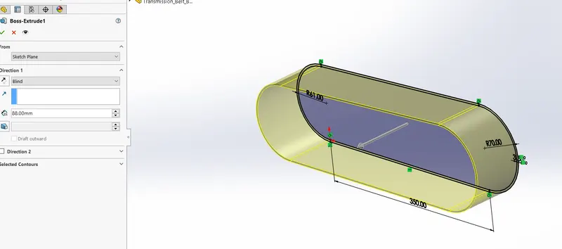
1. Extruded boss/base - used to create a solid feature as shown in figure.
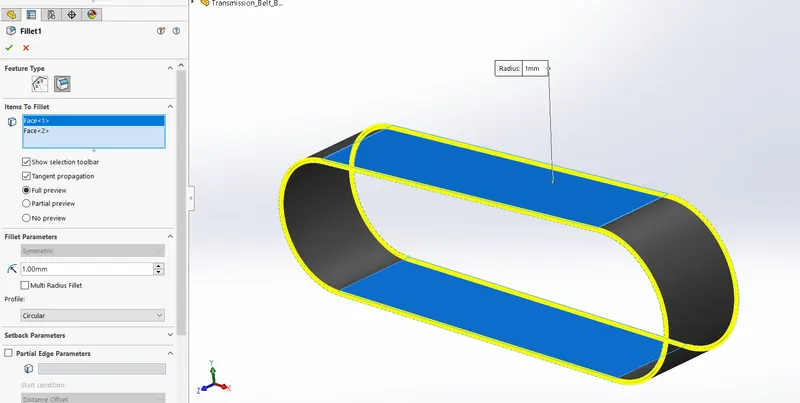
2.Fillet - Used to create rounded internal/external face along with one or more edges. Fillet is shown in figure.
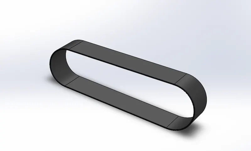
Transmission belt as follows:
2. Side kick stand:
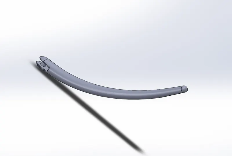
Next part is side kick stand. Here I used ellipse and spline tools to create curved stand.
Sketch Entities:
1. Ellipse - Used to create ellipse shape.
2. Spline - Used to sketch a spline. With the use of spline we get a curved structure.
3. Centre rectangle - Sketches a rectangle with centre point.
4. Line
5. Circle - Used to sketch a circle.
Features:
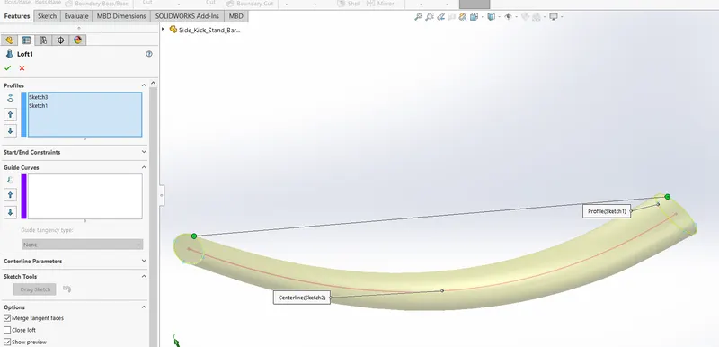
1. Loft Boss/Base - Used to create solid feature between two or more profiles as shown in figure.
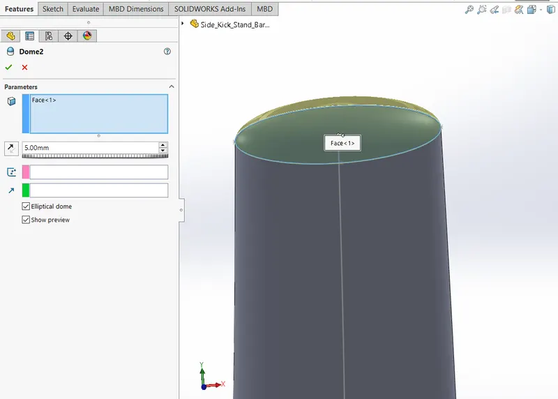
2. Dome - Used to create dome feature on a face as shown in the figure.
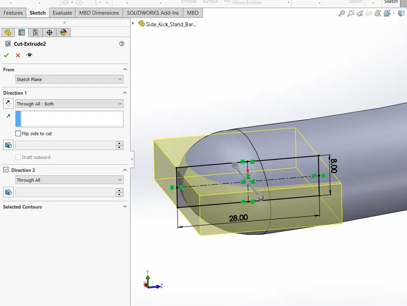
3. Extruded cut - Used to cut a solid model by extruding a sketched profile like as follows.
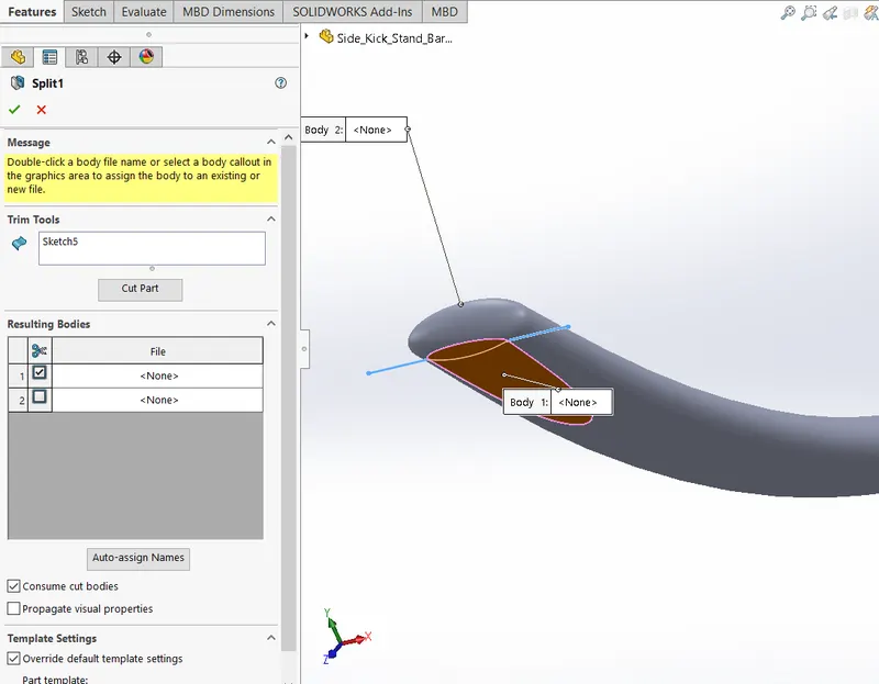
4. Split - Used to create sperate body from a single one.
5. Extruded boss/base
6. Fillet
The side kick stand is shown in the below figure.
3. Front and Rear Fender:
Front Fender
Sketch Entities
1. Line
2. 3 point arc
3. Spline
4. Centre line
Sketch Tools
1. Offset
2. Trim - Used to trim lines
Features
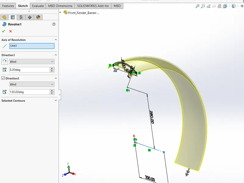
Revolved boss/base - Creates a solid feature around an axis as in the figure.
2. Split
3. Fillet
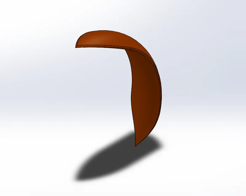
Front fender is shown in the figure.
Rear Fender
Sketch Entities:
1. Line
2. 3 point arc
Sketch Tools:
1. Offset
2. Trim
Features
1. Revolved boss/base
2. Split
3. Fillet
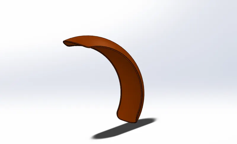
4. Shell - Removes material from a solid body to create a thin wall feature as shown in figure.
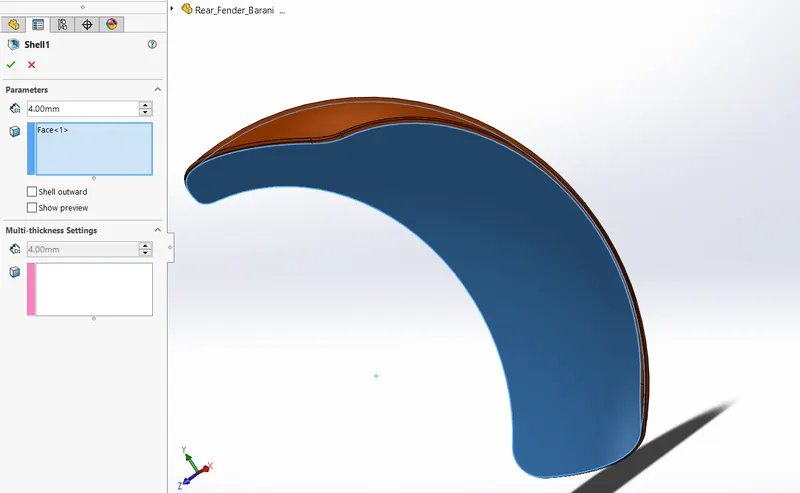
Rear fender is shown in the figure
4. Chain link:
Sketch Entities
1. Circle
2. Line
3. Blocks - Blocks are pre-defined sketches, used when same sketch is required multiple times.
Features
1. Extruded boss/base
2. Fillet
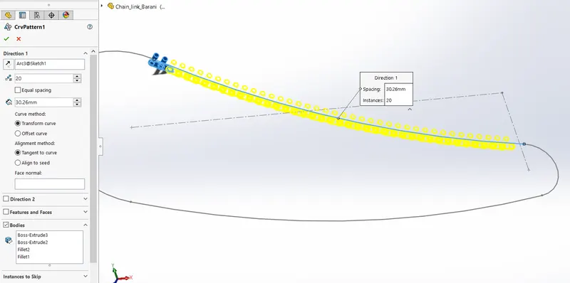
3. Curved pattern - Used to create a pattern along the curve as shown in the below figure.
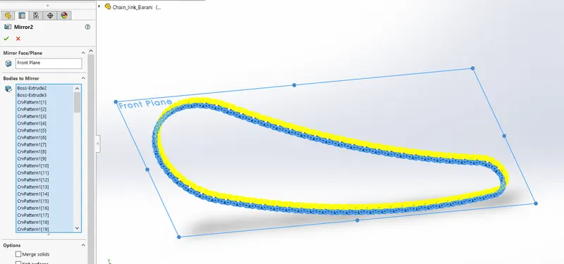
4. Mirror - Used to mirror bodies about face or a plane as in the below figure.
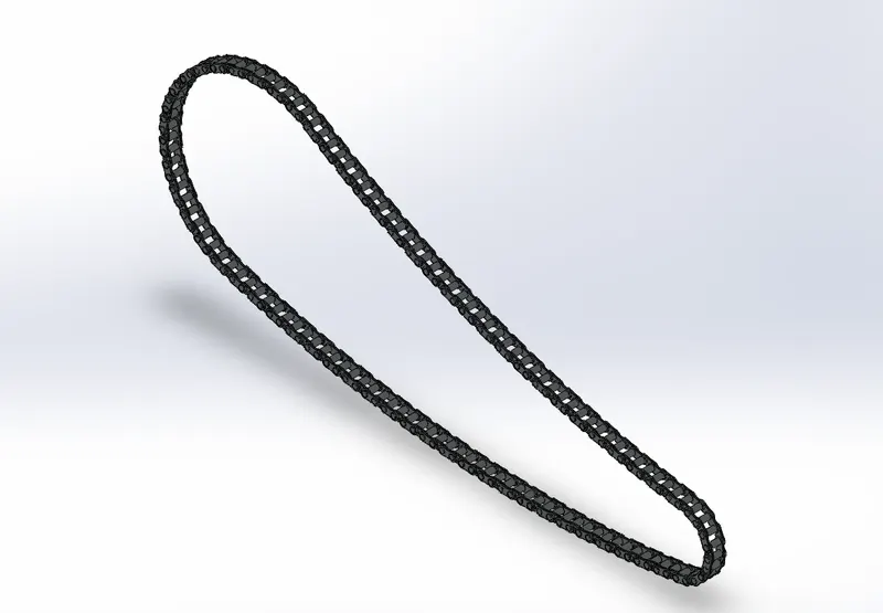
The Chain link looks like as following.
5. Oil Tank:
Sketch Entities:
1. Line
2. Arc
3. Spline
4. Mirror - Used to create a mirror about an axis/centreline.
Features:
1. Extruded boss/base
2.Fillet
3. Shell
4. Combine - Used to combine two or more solid bodies as shown in the figure.
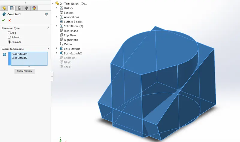
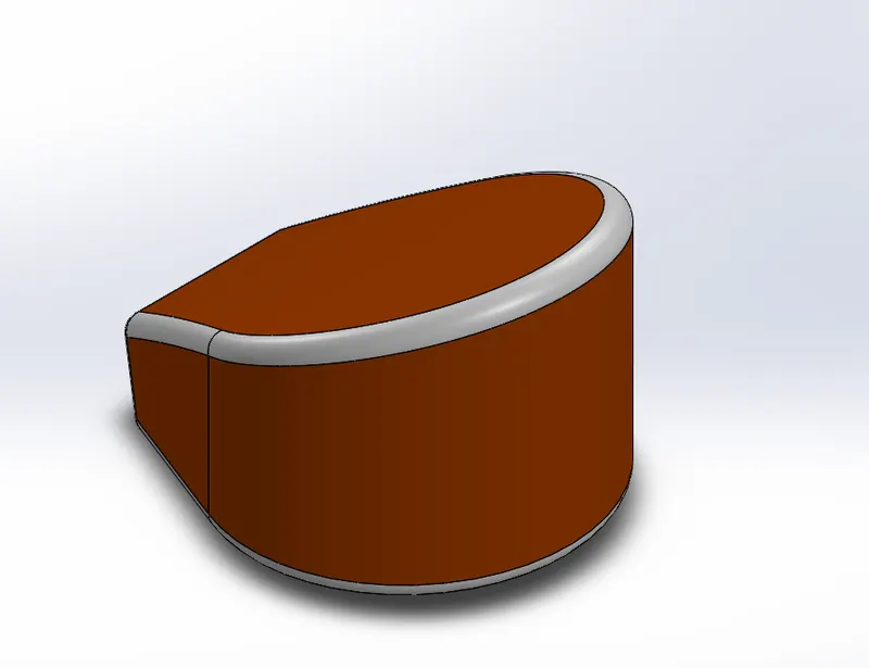
Oil tank is shown in the below figure.
6. Pedal:
Sketch Entities:
1. Line
2. Circle
3. Spline
Features:
1. Extruded boss/base
2. Revolved boss/base
3. Fillet
4. Dome
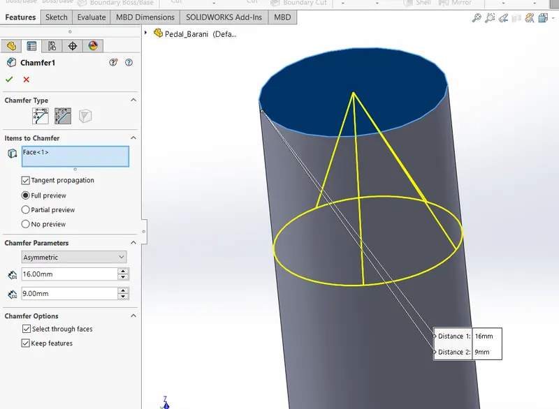
5. Chamfer - Used to create a symmetrical slopping surface at an edge or corner as shown in the figure.
6. Linear pattern - Used to create a pattern in linear direction.
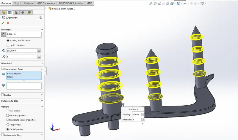
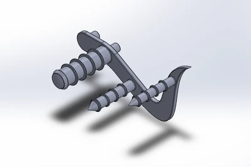
The Pedal of a chopper is shown in the following figure.
7. Front and Rear Wheel:
Front wheel
Sketch Entities:
1. Line
2. Arc/3 point arc
3. Rectangle
4. Spline
Sketch Tools:
1. Offset
2. Trim
3. Convert entities - Used to convert model edges or sketches into sketch segment.
Features:
1. Extruded boss/base
2. Revolved boss/base
3. Extruded cut
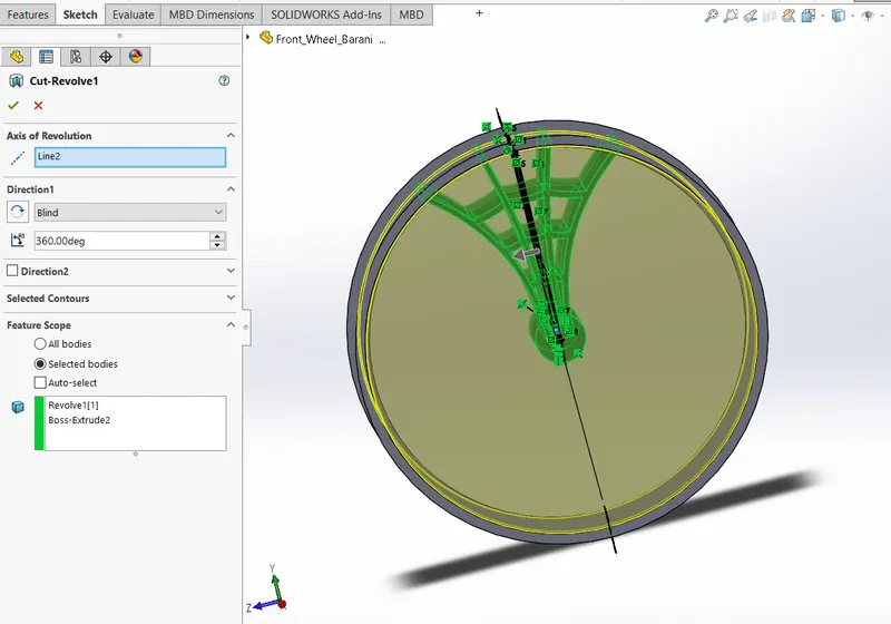
4. Revolved cut - Used to cuts a solid model by revolving a sketched profile around an axis as shown in the below figure.
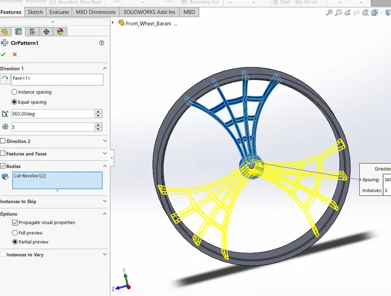
5. Circular pattern - Used to create a pattern on a circular path.
6. Fillet
7. Chamfer
8. Combine
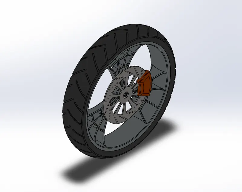
Front wheel part is shown in the below figure.
Rear wheel
Sketch Entities:
1. Line
2. Circle
3. Arc/3 Point arc
4. Rectangle
5. Spline
Sketch Tools:
1. Offset
2. Trim
3. Convert entities
Features:
1. Extruded boss/base
2. Revolved boss/base
3. Extruded cut
4. Revolved cut
5. Circular pattern
6. Fillet
7. Chamfer
8. Combine
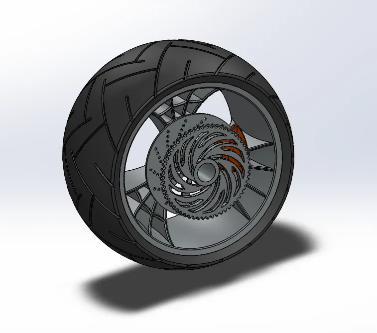
Rear wheel part is shown in the below figure.
8. Front Fork:
Sketch entities:
1. Line
2. Circle
3. Spline
4. Rectangle
Sketch Tools:
1. Trim
2. Convert Entities
3. Offset
Features:
1. Extruded boss/base
2. Revolved boss/base
3. Fillet
4. Linear pattern
5. Extruded cut
6. Mirror
7. Combine
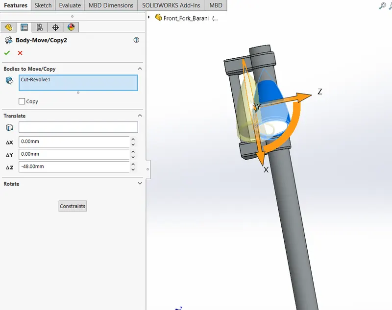
8. Move/copy - Used to move the solid bodies as shown in the following figure.
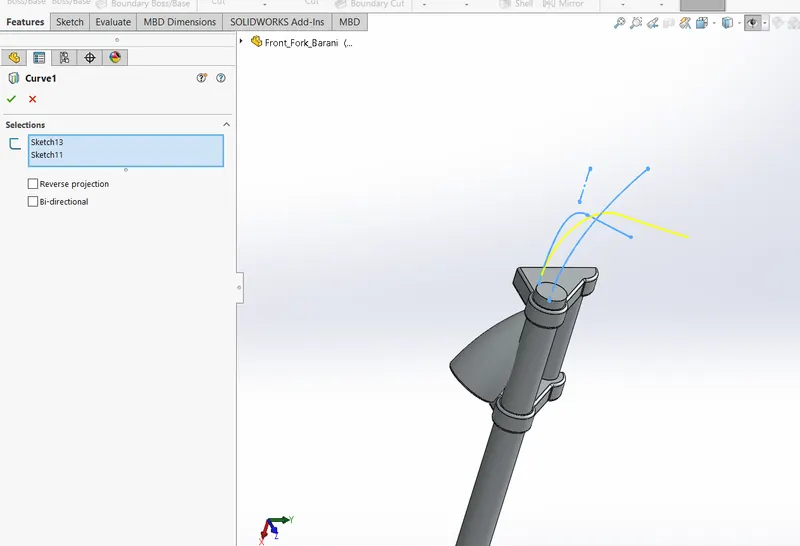
9. Project curve - Used to create projected curve from a two different curves as shown in the figure.
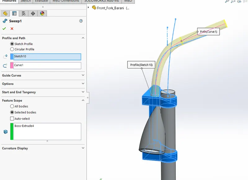
10. Swept boss/base - Used to sweep a closed profile along a open or closed path to create a solid feature as shown in the figure.
11. Plane - Used to create a plane.
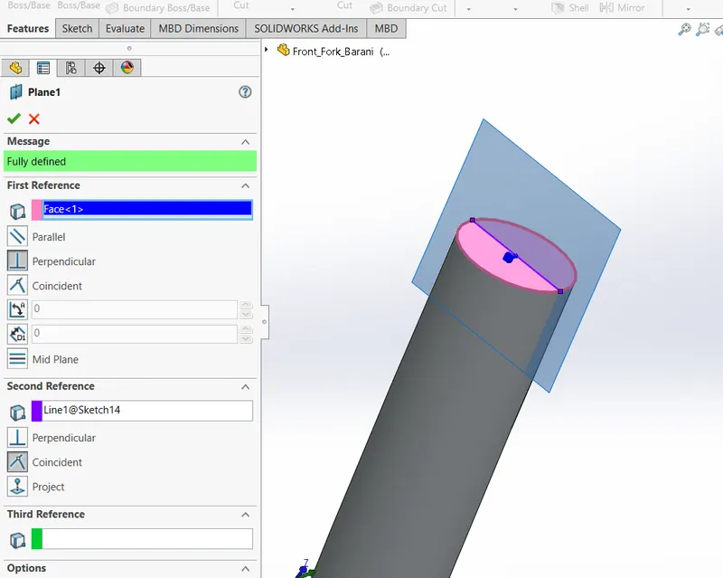
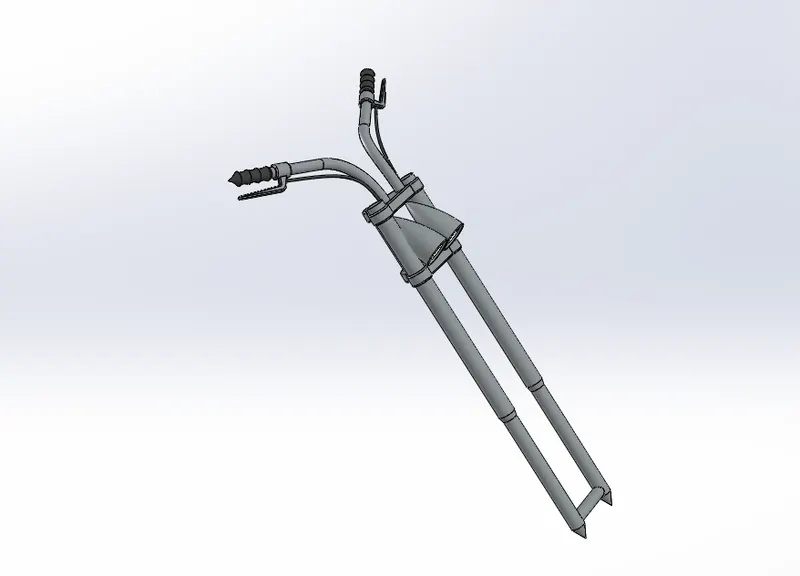
Front fork of a chopper shown in the following figure.
9. Chassis:
Sketch Entities:
1. Line
2. Circle
3. Spline
4. Rectangle
5. Arc
Sketch Tools:
1. Trim
2. Convert entities
3. Offset
Features:
1. Project curve
2. Swept boss/base
3. Mirror
4. Extruded boss/base
5. Extruded cut
6. Chamfer
7. Fillet
8. Plane
9. Dome
10. Split
11. Combine
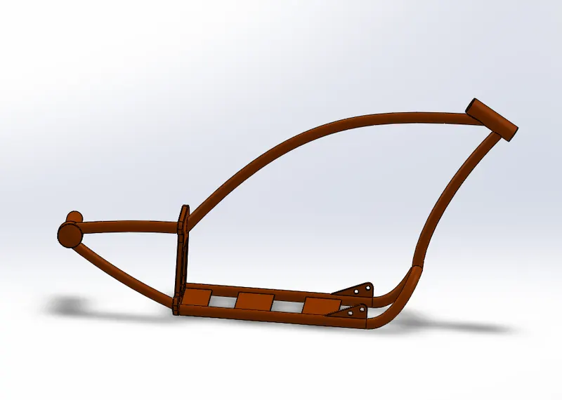
Chassis of American chopper is shown in the following figure.
10. Engine:
Sketch Entities:
1. Line
2. Circle
3. Rectangle
4. Spline
Sketch Tools:
1. Offset
2. Trim
3. Convert Entities
Features:
1. Extruded boss/base
2. Fillet
3. Revolved boss/base
4. Plane
5. Circular pattern
6. Dome
7. Extruded cut
8. Chamfer
9. Linear pattern
10. Mirror
11. Split
12. Swept boss/base
13. Combine
14. Project curve
15. Composite curve - Used to merge two different curves and makes into single curve as shown in the figure.
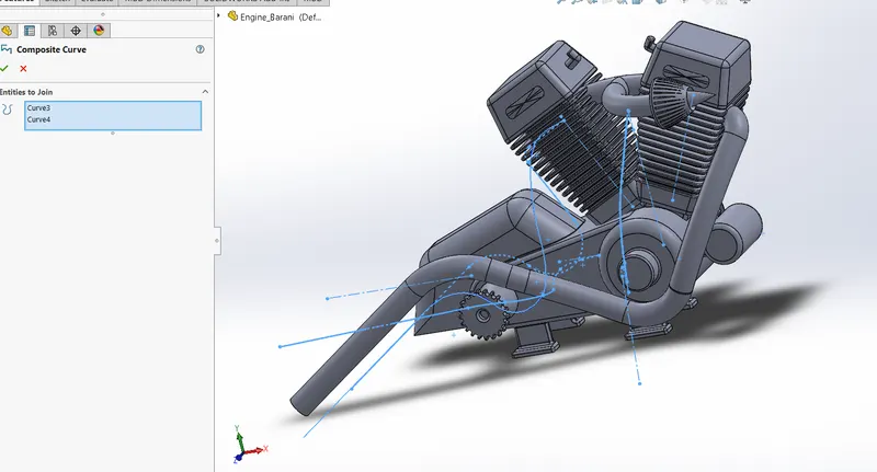
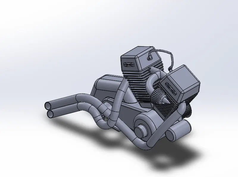
Engine part drawing is shown in the below figure.
11. Gas Tank:
Sketch Entities:
1. Line
2. Circle
3. Spline
4. Arc
Sketch Tools
1. Offset
2. Convert Entities
3. Trim
Features:
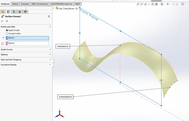
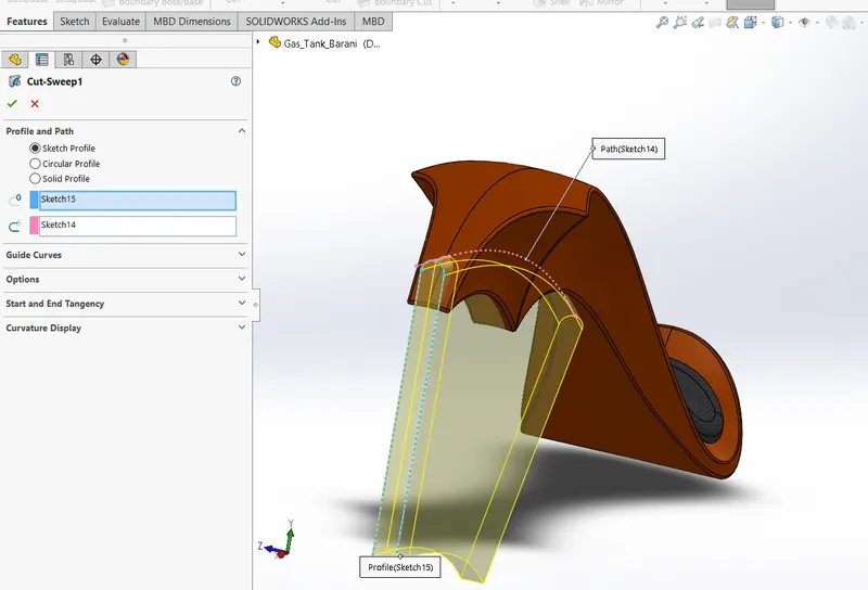
1. Surface sweep - Used to sweep the curve along the surface as in the figure.
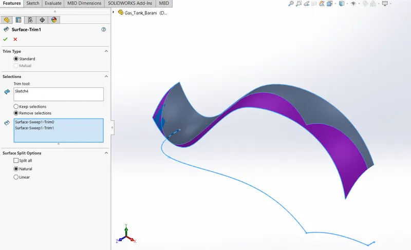
2. Surface Trim - Used to trims the surface as in the following figure.
3. Plane
4. Project curve
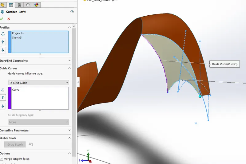
5. Surface loft - Used to loft the curve along the surface as shown in the figure.
6. Surface boundary - Used to create a boudary for the surface as shown in the figure.
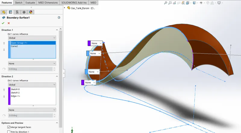
7. Mirror
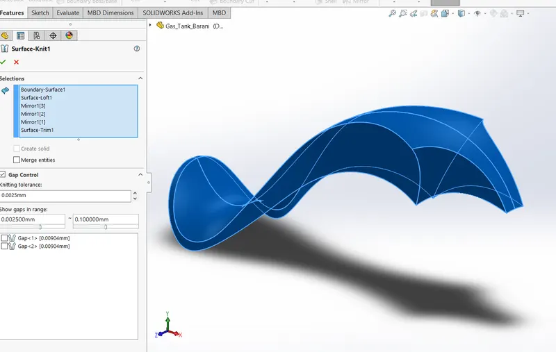
8. Surface knit - Used to combine two or more faces and surfaces into one as shown in the figure.
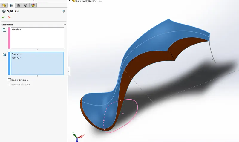
9. Split line - Used to divide a selected face into multiple separate faces as shown in the figure.
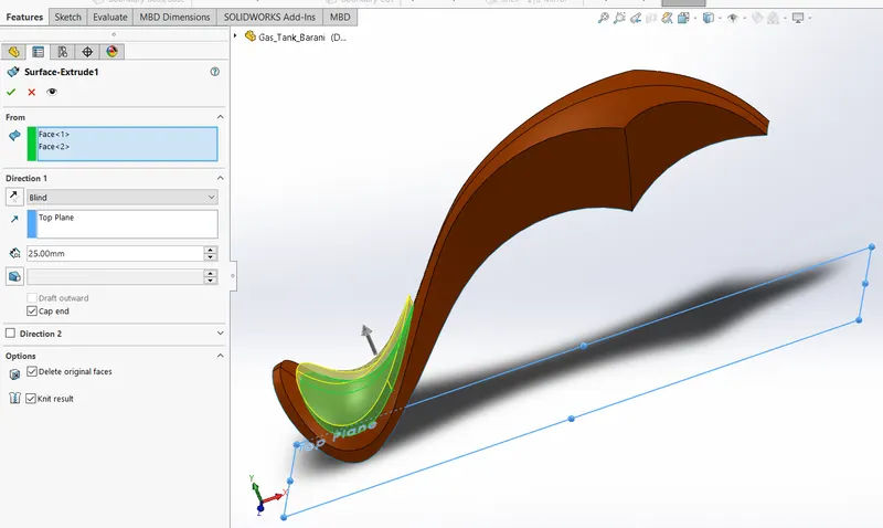
10. Surface extrude - Used to extruded surface for the seat as shown in the figure.
11. Fillet
12. Shell
13. Swept cut - Used to cut a solid model by sweeping a closed profile along on open or closed path.
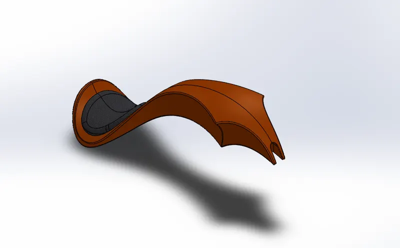
Gas tank of an American chopper as shown in the below figure.
Assembly of American chopper:
The next step is to assemble all the created parts by using assembly option in solidworks. Then parts can be inserted one by one by using insert option. in this case I have first inserted Chassis part, because it's a base to attach all other parts around it. Assemble can be done by Mate command. There are various mate commands are available like standard mates, Advanced mates and Mechanical mates. Here we used mostly standard and advanced mates only. Followings are the mates used in the assembly.
1. Coincident mate
2. Distance mate
3. Concentric mate
4. Limit angle mate
5. Width mate
6. Angle mate
7. Parallel mate
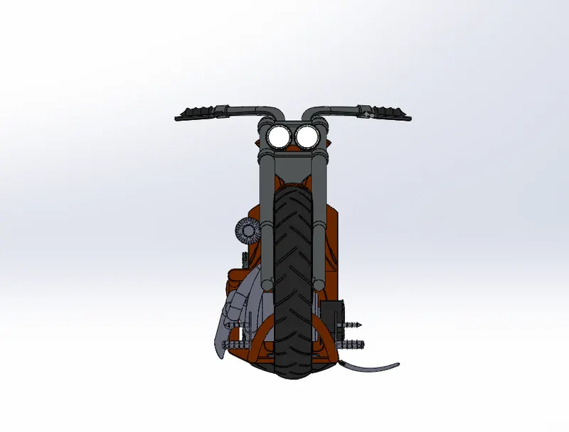
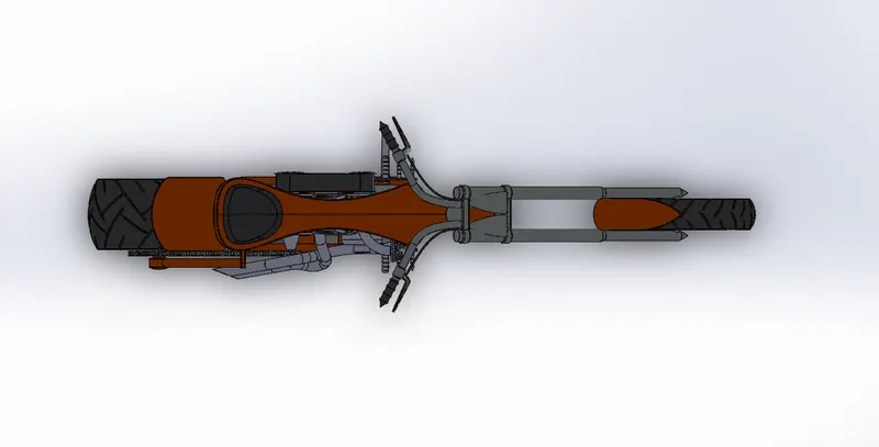
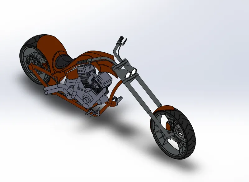
Assembled images of Chopper are as follows:
Front view:
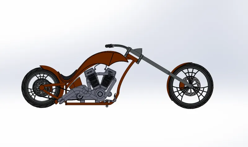
Right side view:
Top view:
Isometric view:
Decals:
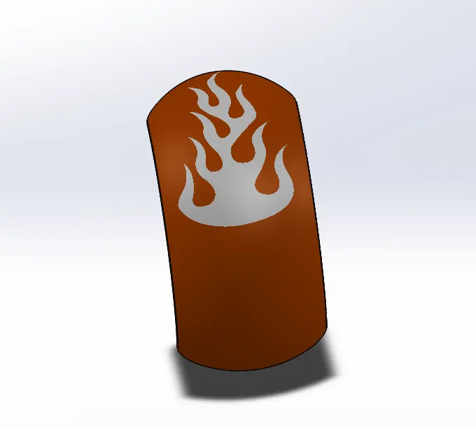
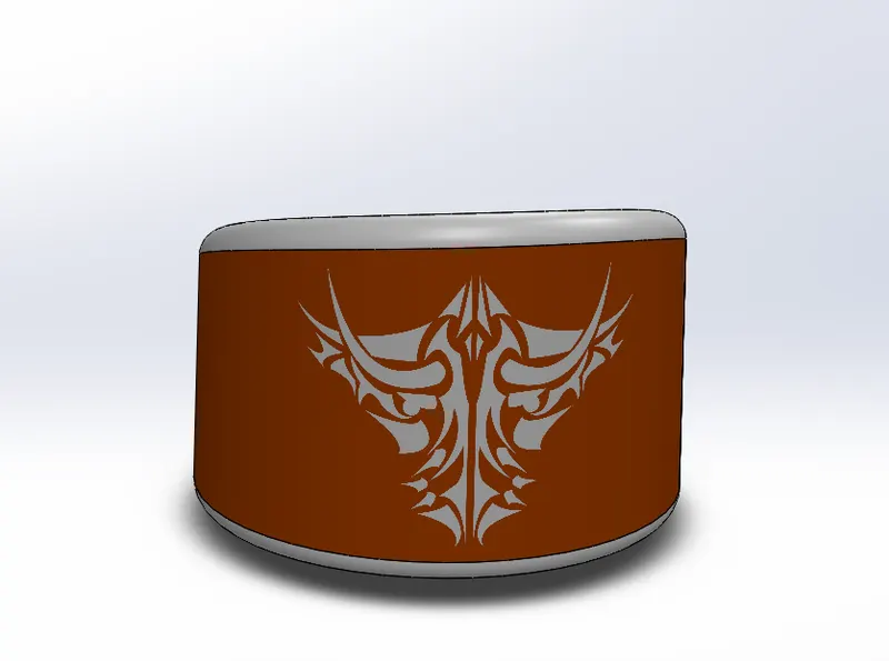
Decals are an adhesive lable applied to the product or artwork that is pad printed. Here I have added decals to the Rear fender, Oil tank and Gas tank. Following are images after addition of decals to the assembly.
Rear Fender
Oil Tank
Gas Tank
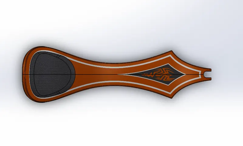
American chopper after adding decals:
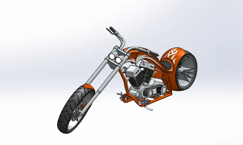
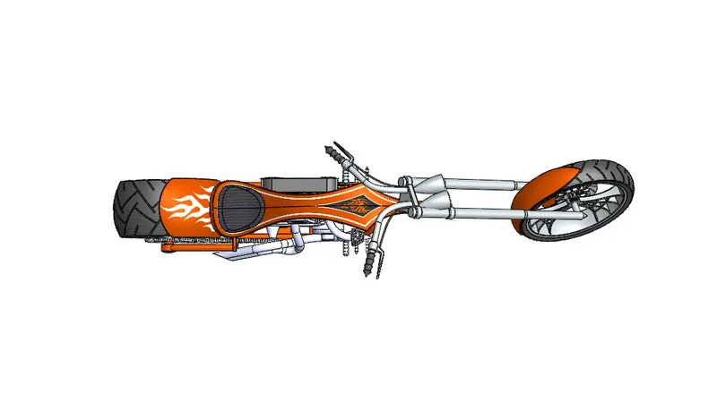
We can add camera to get better viewing experience. I have added camera to the chopper as shown in the following figure.
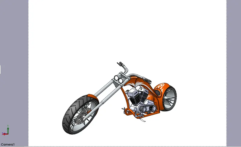
PHOTO VIEW 360 RENDERING:
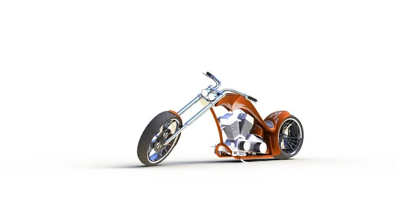
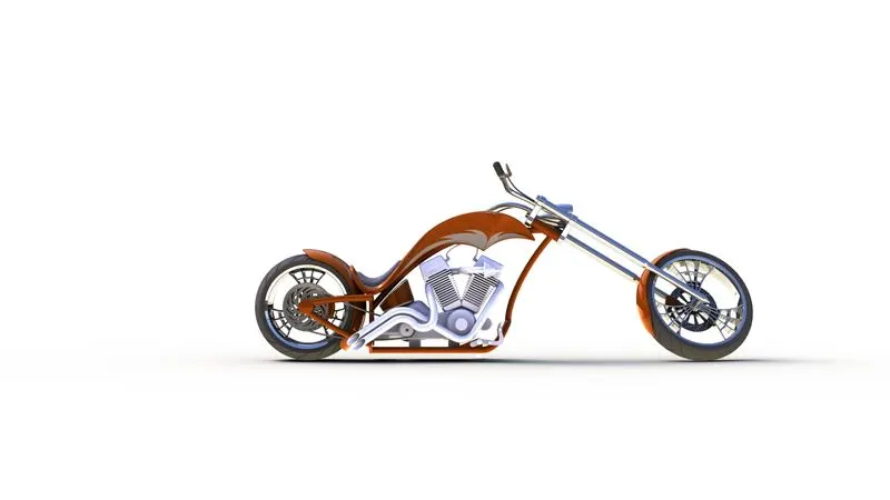
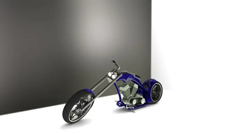
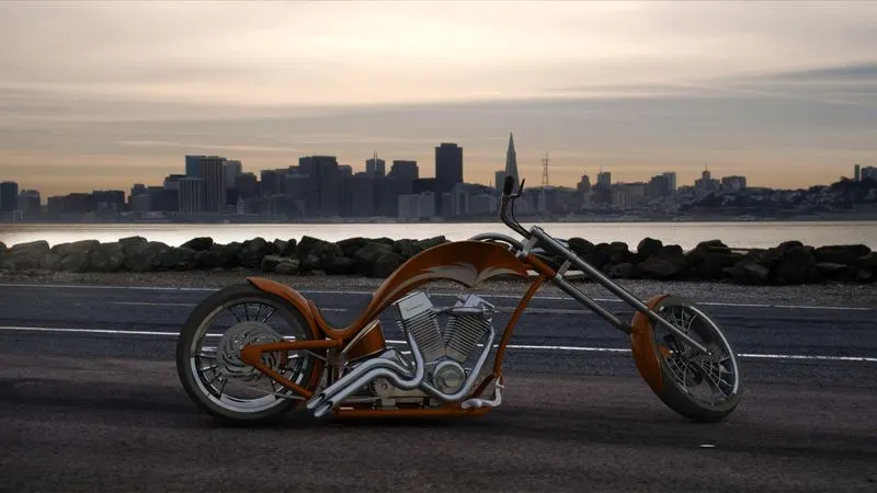
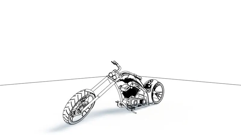
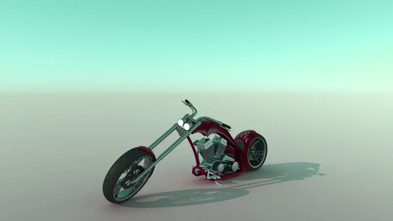
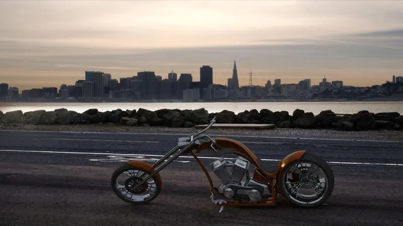
Photo View 360 is a solidworks add in that produces photo-realistic renderings of solidworks models. The rendered image incorporates the appearances, lighting, scene, decals included with the models. I have created 5 five different rendering images by varying lights, scenes and different camera views. Look at the rendered images following.
CONCLUSION:
I have learnt and understood the basic features of solidworks by creating American chopper bike with photo-realistic rendering. Now, I can able to use those features and rendering to design the parts.