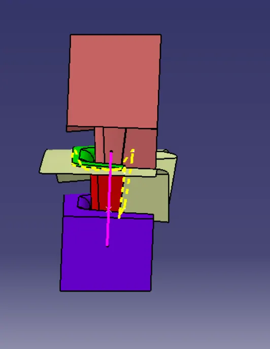
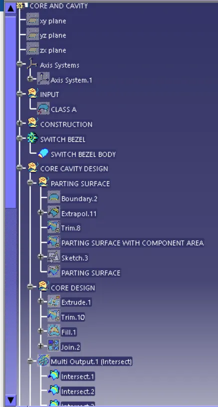
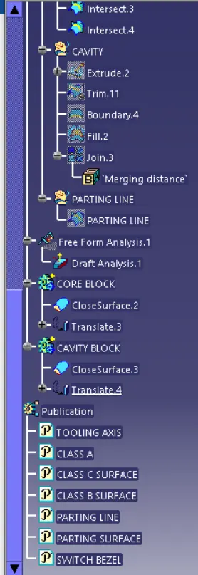
Week 8 - Challenge 5 - Core & Cavity Design
CORE AND CAVITY DESIGN
Aim:- To design the parting surface and parting line and core and cavity blocks for the switch bezel designed in the earlier challenge.
Procedure:-
First, the continuity should be checked in the given Class-A surface. By using the boundary option.
Tooling axis:
- Extract the base of the switch bezel using the multiple extract option. Create an option on it using on surface option.
- Insert axis system in the point, create a sketch on it using the YZ plane.
- Make an intersection on it, draw two inclined lines and the point create a line which is the tooling axis Y.
- By using the same method create a sketch on the XZ plane that makes an intersection on it. Draw a line on the intersection and draw another line which is 5 to 6 degrees from the first line. Which is the tooling axis X.
- Create a bisecting line using the X & Y tooling axis we get the tooling axis and publish it.
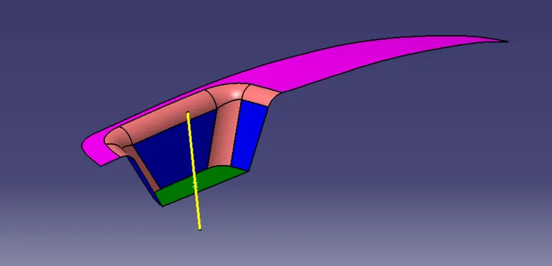
Draft analysis
- For plastic parts, the nominal draft angle is 3 deg. But even 7deg is allowed for the subassemblies like ribs and slots.
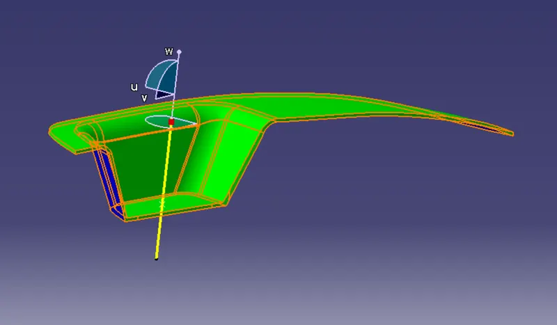
- First, the compass is moved to the part (the compass should be placed on the tooling axis) which is used to define the new current draft direction, then lock the draft direction using the lock icon.
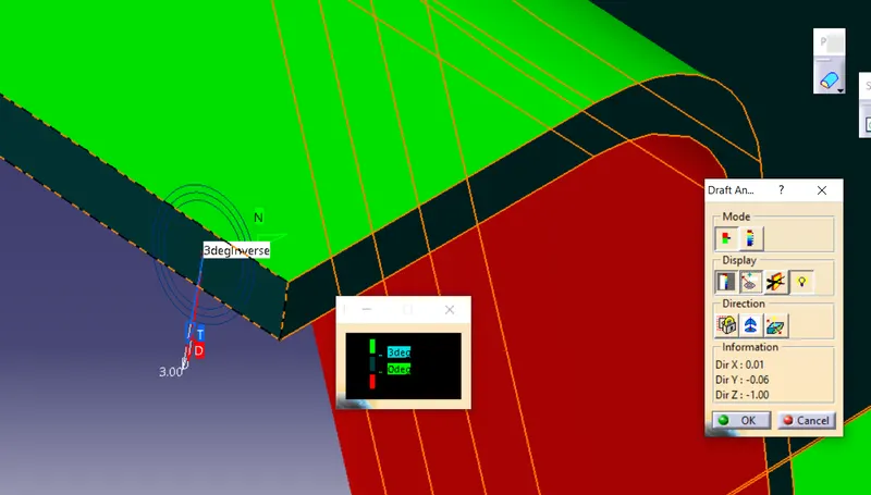
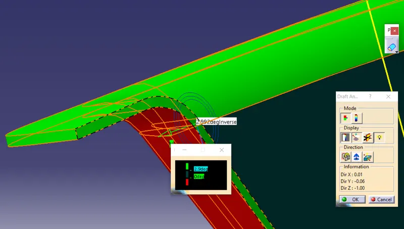
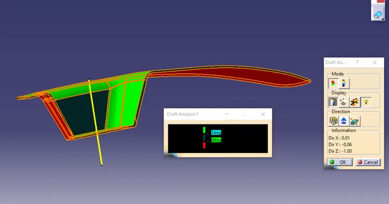
- The color chart indicates the various condition of the draft angle. The green color indicates that the part passes and can be used for further operations.
- By using the analysis under the running point icon we can check the draft angle at the various surfaces of the component.
- There are two modes in the draft analysis quick mode and the fully detailed model.
- If the surface satisfies the 3deg then it shows in green in color if not appears in red color.
Parting Surface:-
Parting surfaces are used to separate the mold cavity from the core.
Designed for the removal of the plastic product and the old slug, the parting surface is where the core meets the cavity and is usually located at the largest section of a product.
First, extract the outer boundary of the class surface and extrapolated it at a particular length.
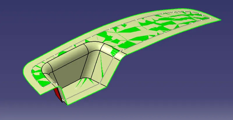
For parting surface creation, first, trim the extrapolated class A surface with class C surface.
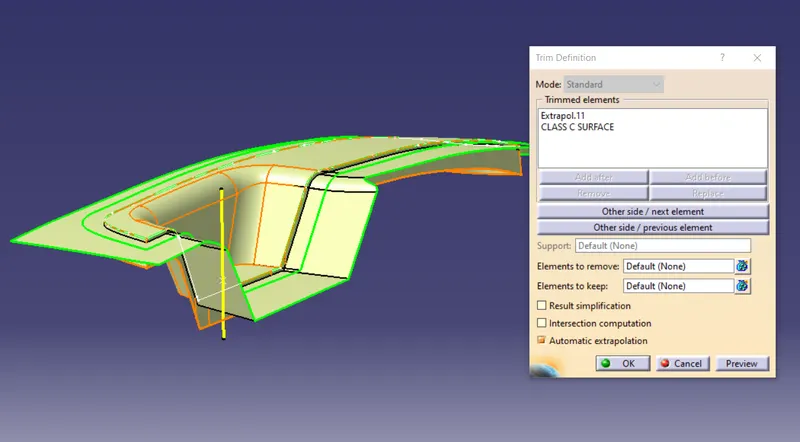
Then Trim the class B surface with the last trim surface which is the final parting surface.
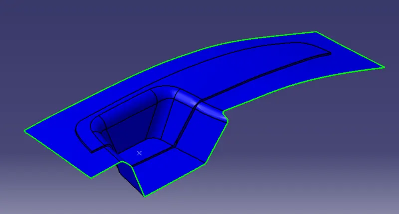
Parting Line:-
A parting line is the line of separation of the plastic part where the two halves of the plastic injection mold meet. The line actually indicates the parting ‘plane’ that passes through the part. Within more basic plastic part design plans this plane can be a simple, flat surface, but it is often a complex form that traces the perimeter of the part around the various features that make up the part’s outer ‘silhouette’.
For parting line creation first, intersect the class C surface with our parting surface.
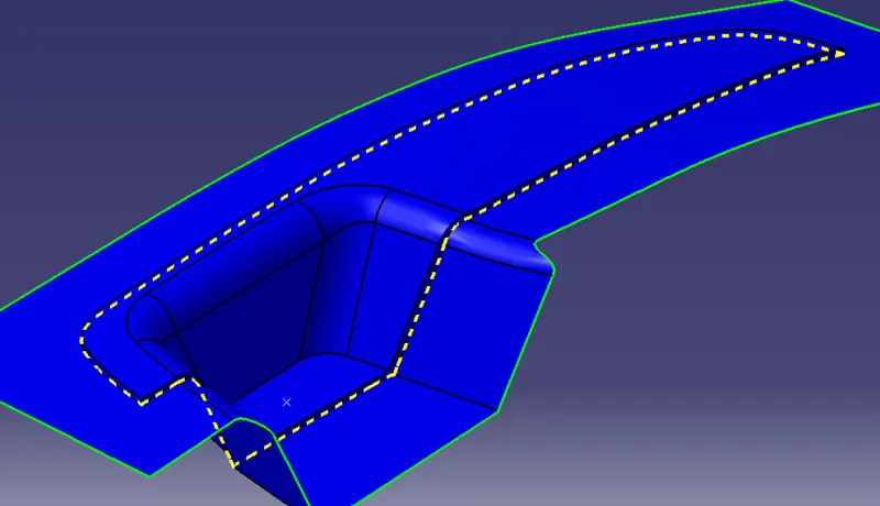
Then slit the last intersection with our parting surface, which is our parting line.
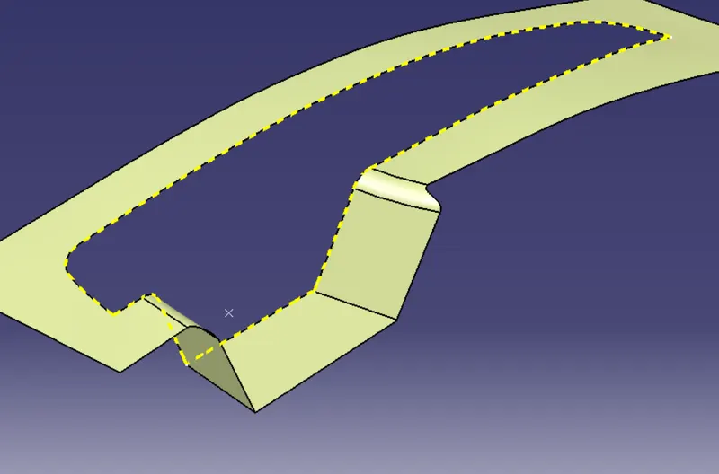
Core design:-
A core is the side of the tool where the plastic part is injected from. Also known as the bottom half of the tool. The upper half of the mold is called the Core.
For core design first draw the outer boundary of the core section by using a sketch on the XY plane, and extrude that.
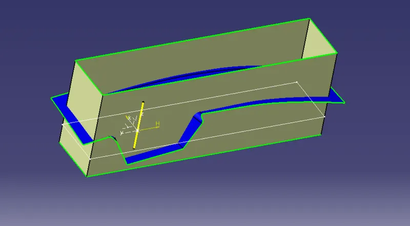
Then trim the outer extruded surface with the parting surface.
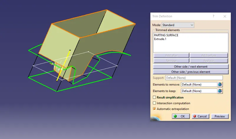
Then make the closed boundary at the top section and closed that boundary by using the fill command, then finally join the top fill surface with the core surface.
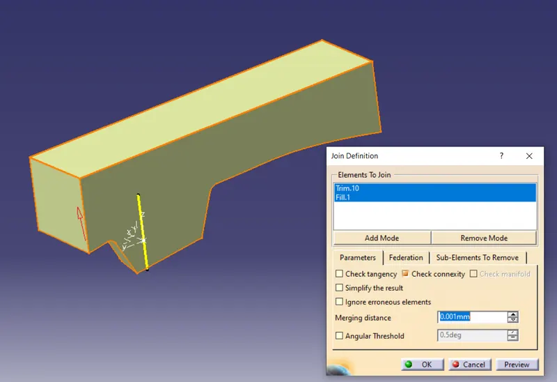
Finally, make the surface core into a solid body core by using the closed body command that is in part a workbench.
This is the final core side half.
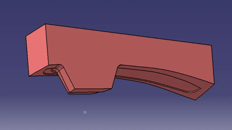
Cavity:-
A mold is a hollow form typically made from stainless steel that has plastic injected into it to manufacture a plastic part. The plastic is inserted into the mold cavity, which is a hole in the mold shaped like the desired part.
The cavity block first draws the outer boundary then extrudes the outer boundary of the cavity block.
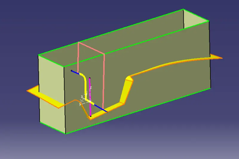
Then trim that surface with our parting surface.
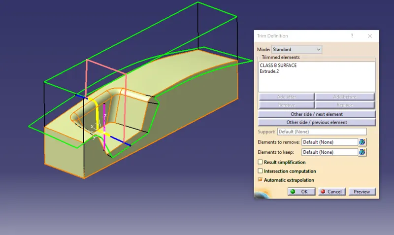
Finally, close the bottom boundary by using the boundary option then fill the closed boundary with the fill command, and finally join with each other by using the join command.
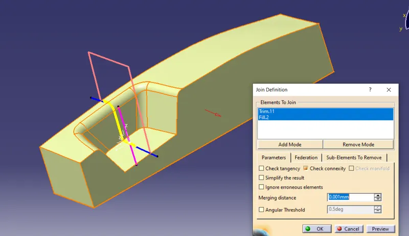
Finally, make the surface cavity into a solid body cavity by using closed body command that is in part a workbench.
This is the final cavity side half.
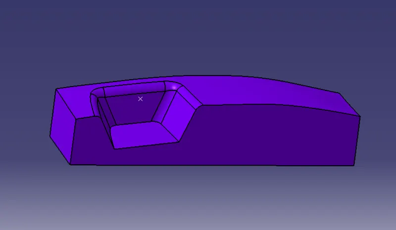
Result:-
Designed the parting surface and parting line and core and cavity block for the switch bezel designed by using Catia V5 software.
core and cavity
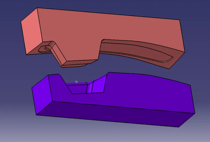
Isometric view
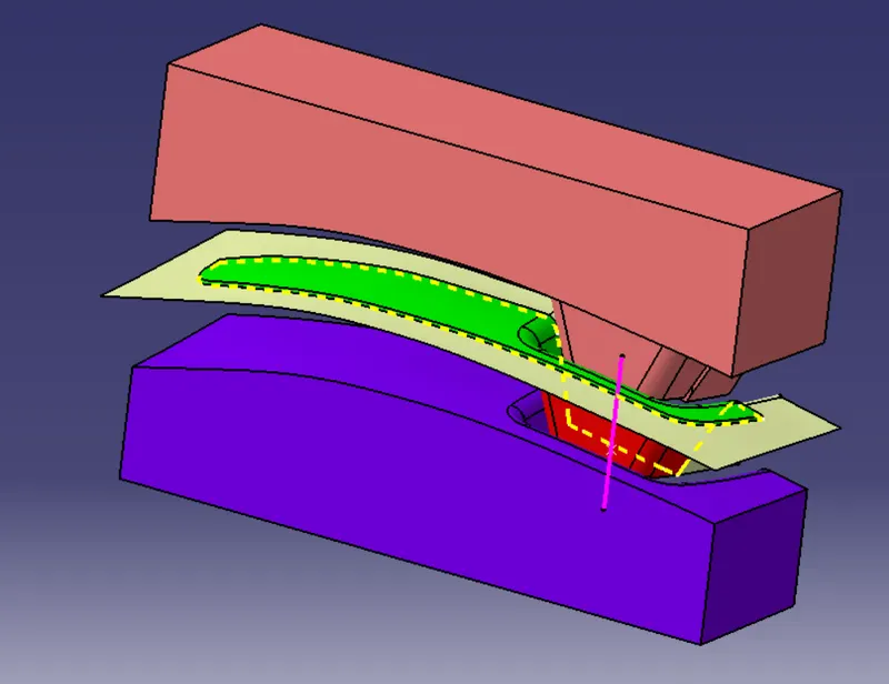
Front view
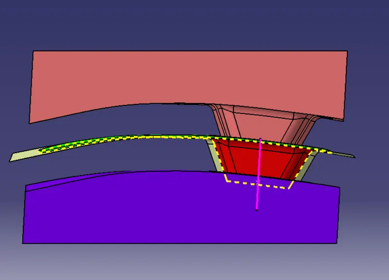
Top view
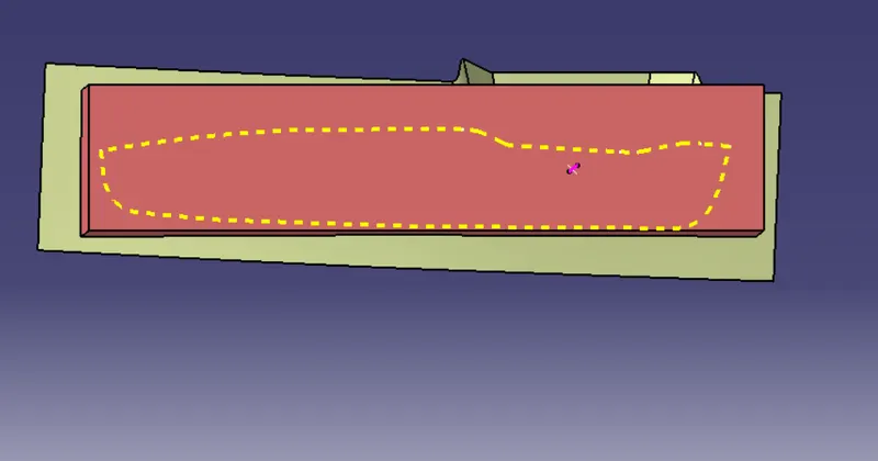
side view