Week 8 - Challenge 5 - Core & Cavity Design
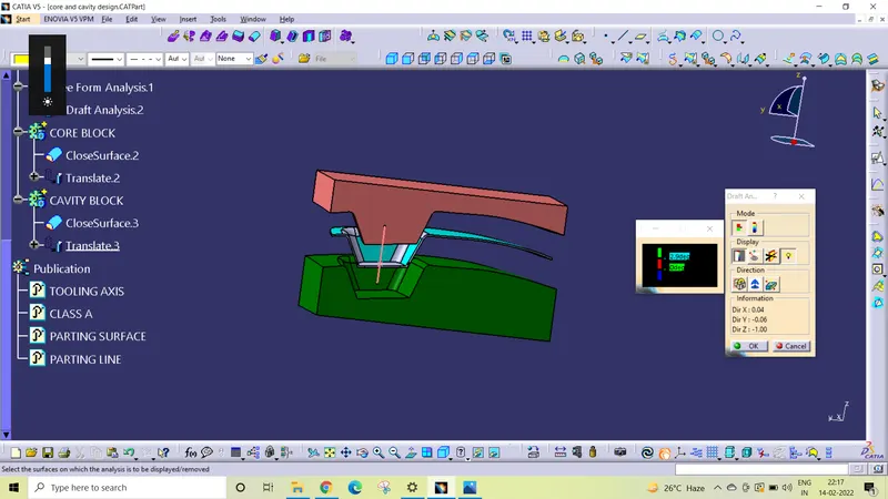
objective: To Create the Core and cavity blocks for the switch bezel.
INTRIDUCTION
When designing a plastic injection mold, the selection of the parting surface is an important design factor. With a reasonable parting surface selection, the mold structure can be simpler, making it easier to mold and release the plastic product, with product quality guaranteed. If the parting surface is inappropriately selected, mold structure becomes complex, making it difficult to mold the plastic product, thus affecting product quality. Therefore, the selection of the parting surface is of great importance to the design of mold structure.
Definition of Parting Surface
Designed for the removal of the plastic product and the cold slug, the parting surface is where the core meets the cavity, and usually locates at the largest section of a product.
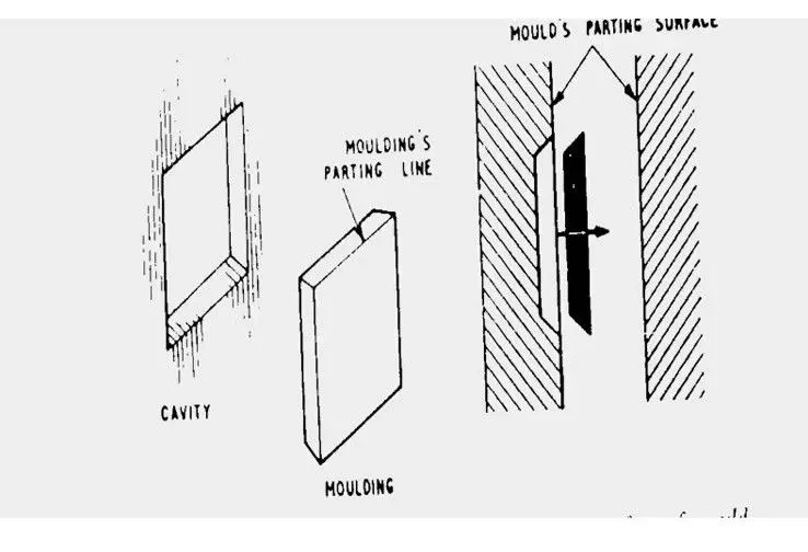
Design parting surface should follow the following principles:
- Design the injection mold structure as simple as possible. Avoid or reduce side parting as much as possible to reduce the complexity of mold making.
- Ease of de-molding. As far as possible, for instance, the plastic parts should stay in fixed halve of the injection mold and ejected by ejection system, avoid side de-molding action.
- Ensure the dimensional accuracy of themolded parts Try to make the parts with similar dimensional accuracy requirements in the same module to reduce manufacturing and assembly errors.
- Ensure appearance requirement of the molded parts. Flash or mismatch occurs usually on parting surface, so the parting surface should not be designed on any high quality requirement surfaces.
- Ensure adequate venting. If possible, parting surface should be place at the end of the mold flow. This is going to be a good advantage of filling and venting.
Parting Lines
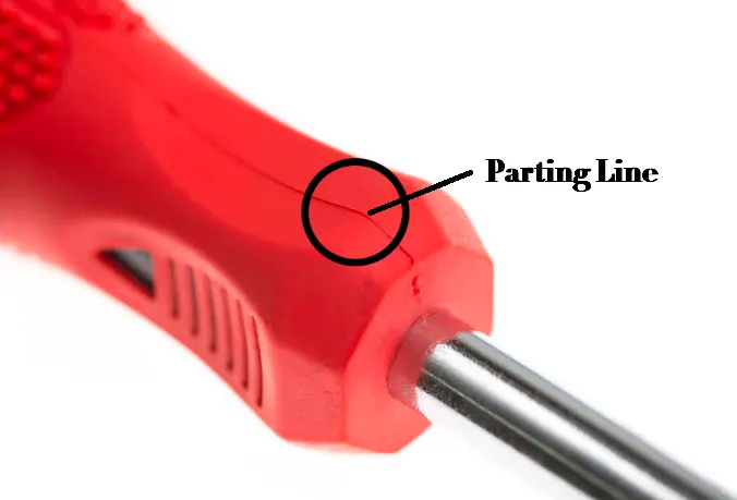
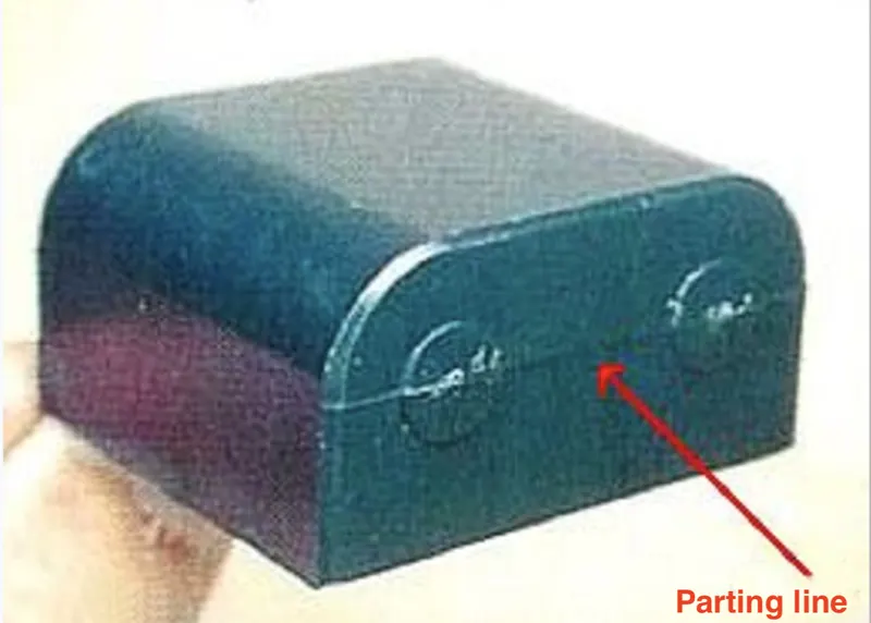
A parting line is an inevitable part of injection molded products. It is the line of separation between where two halves of a mold meet.
How are Parting Lines Formed?
The formation of parting lines is a result of the injection molding process itself rather than any error. Generally, the mold machinists use for producing injection molded parts is usually divided into two halves (known as the fixed half and the moving half). When the machinists close the mold body, the mold halves (known as the core plates) and the surface of the cavity make a parting line between both halves of the part.
Types of Parting Lines
The type of parting line in injection molding generally depends on the specific function and structure of the plastic part. However, there are five main types which are: vertical, stepped, inclined, curved, and integrated parting lines.
1. Vertical Parting Line
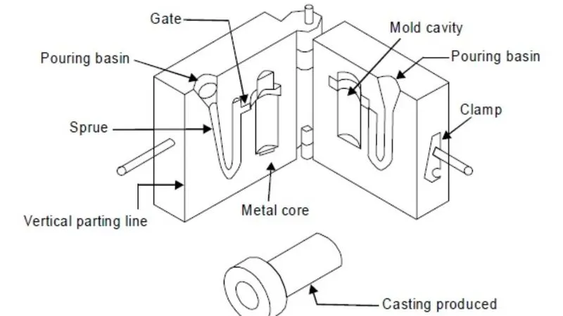
The vertical parting is the most popular of all parting lines in plastic design. Machinists form the vertical parting line in a perpendicular direction from the mold opening direction.
2. Beveled Parting Line
The plastic parting line is in a beveled shape here
3. Curved Parting Line
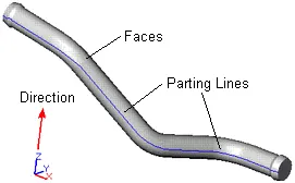
Here, machinists build the mold to create a curved parting line.
4. Stepped Parting Line
Here, machinists make the plastic parting line in a stepped shape. For this type of parting line, there’s usually a large force on one side of the cavity. This causes a relative possibility of sliding between the fixed and moving halves of the mold.
This force can then be canceled out by generating an injection force on both sides of the cavity. There’s also a possibility of the generated force being too large or too small. If the force is too small, machinists compensate for it with a guide pin. Here, the effect of the smaller unbalanced injection force might not be significant on the final product.
However, if the force is too large, a couple of solutions can be applied. Here are a few examples:
- Make a wedge-shaped insert on one side of the cavity. This way, the insert offloads some of the injection force. Hence, the molds can maintain the relative position between the cavity and the core.
- Lay out the molds in a symmetrical shape. This helps to make the injection force applied to both sides balanced. The structure of the mold should also be made as compact as possible to support the symmetrical arrangement.
5. Comprehensive Parting Line
As the name suggests, this is one of the most carefully done parting lines in plastic design. Machinists and designers work on this parting line based on the structure of the plastic part. They could combine all other parting lines to make a comprehensive plastic parting line.
steps followed.
First import the Class A surface of base bracket model in CATIA
Check the connectivity of Class A surface using boundary option. Ensure there is no gap between the two surfaces.
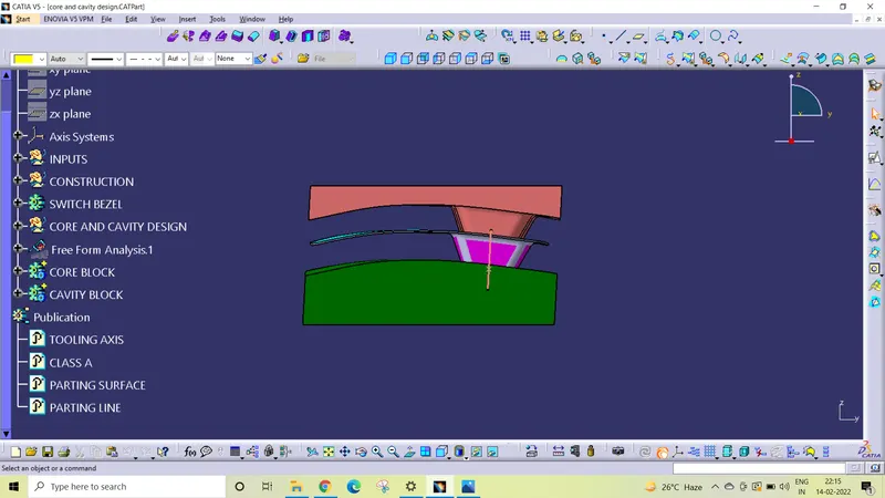
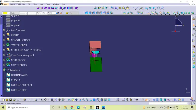
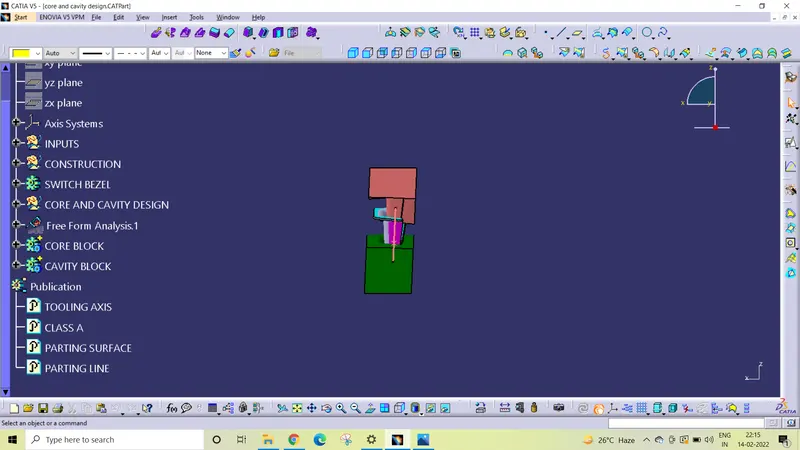
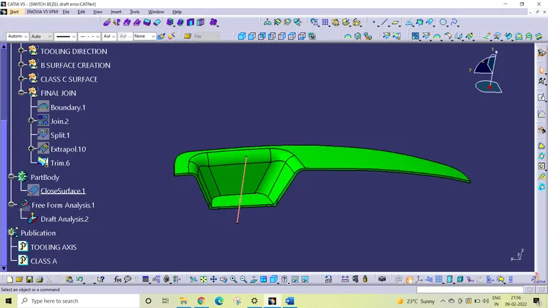
Tooling axis creation we need to which direction is better for creating tooling axis.
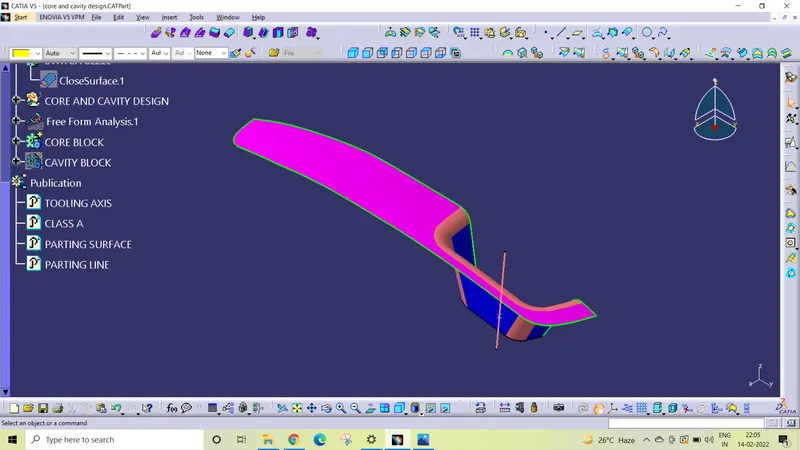
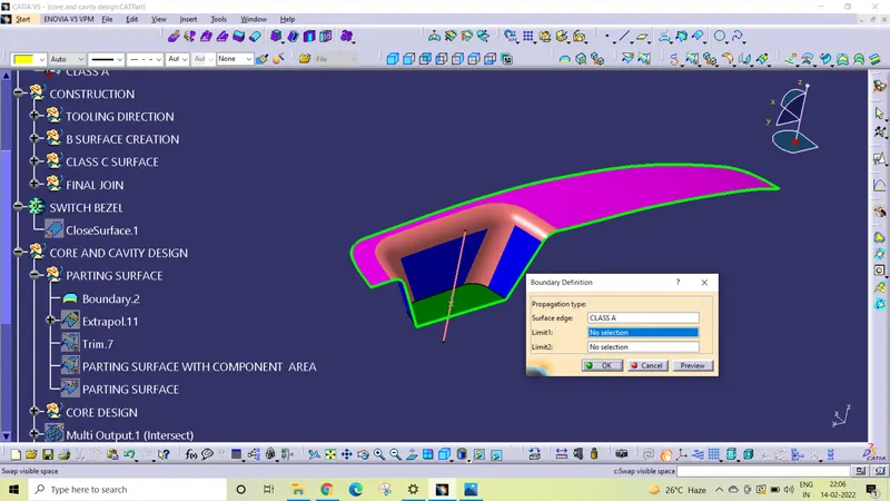
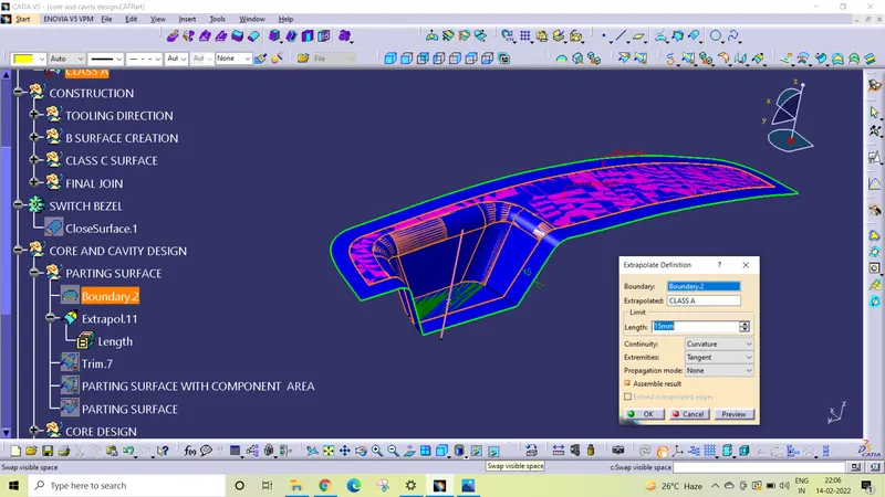
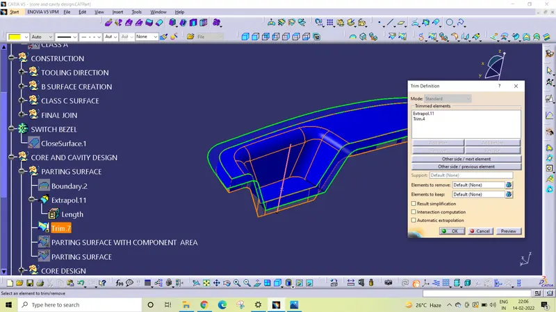
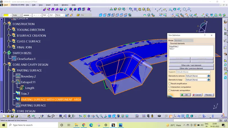
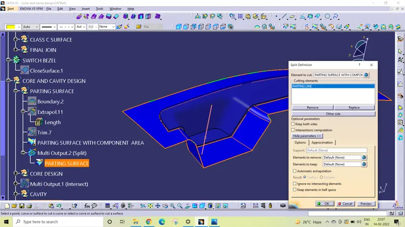
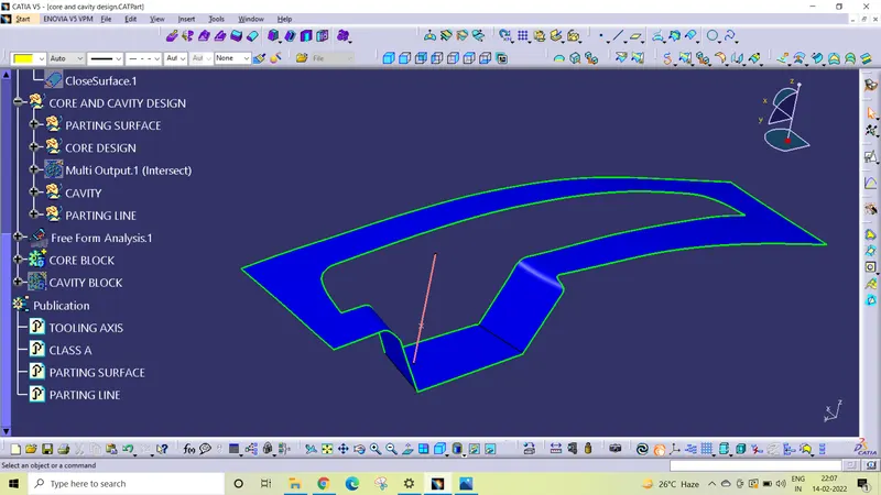
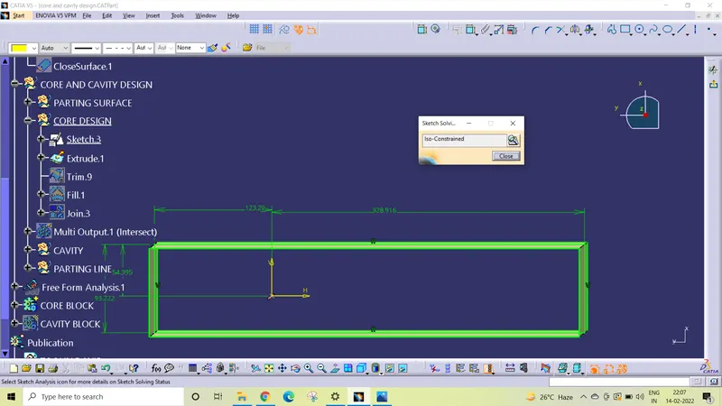
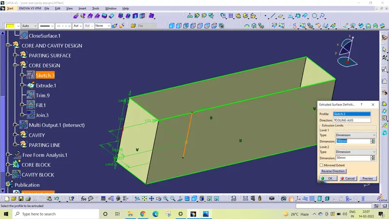
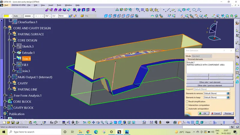
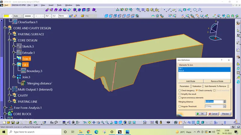
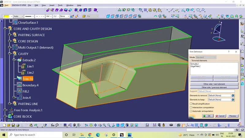
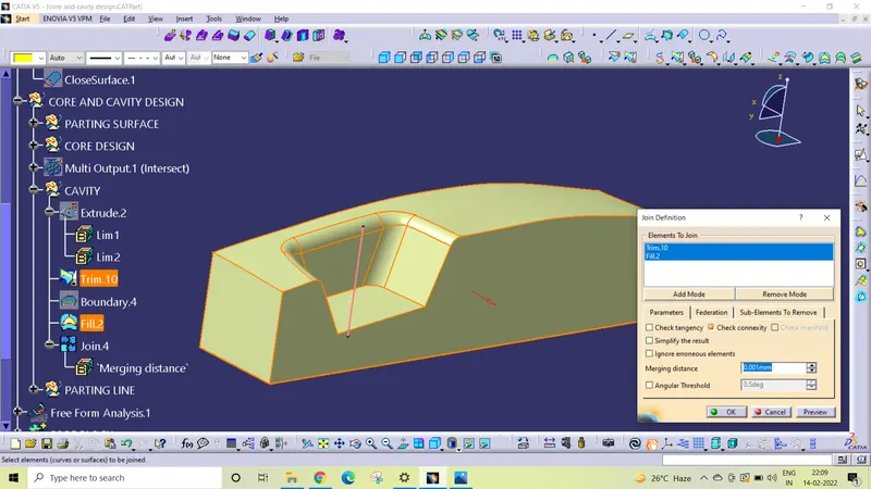
ISO VIEW
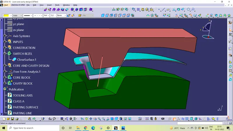
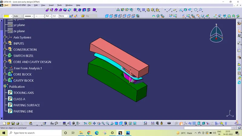
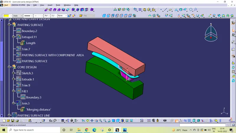
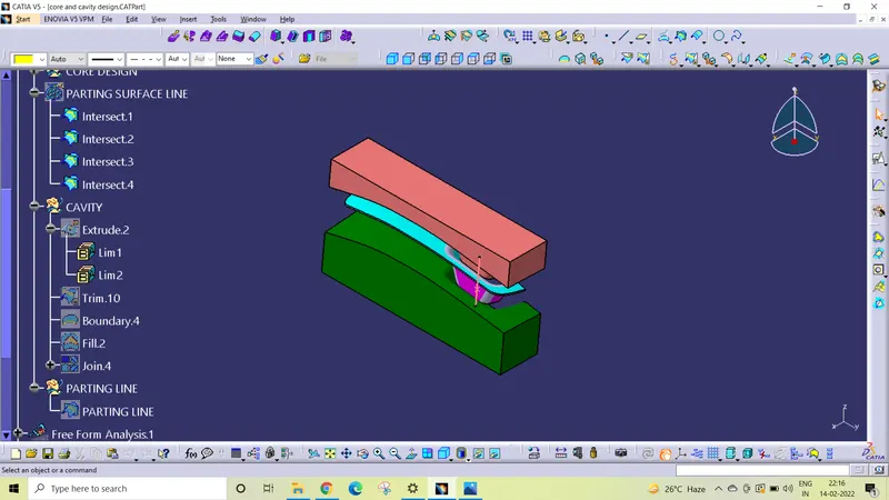
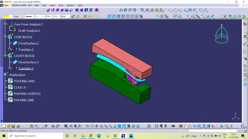
TREE STRUCTURE
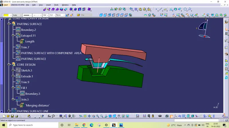
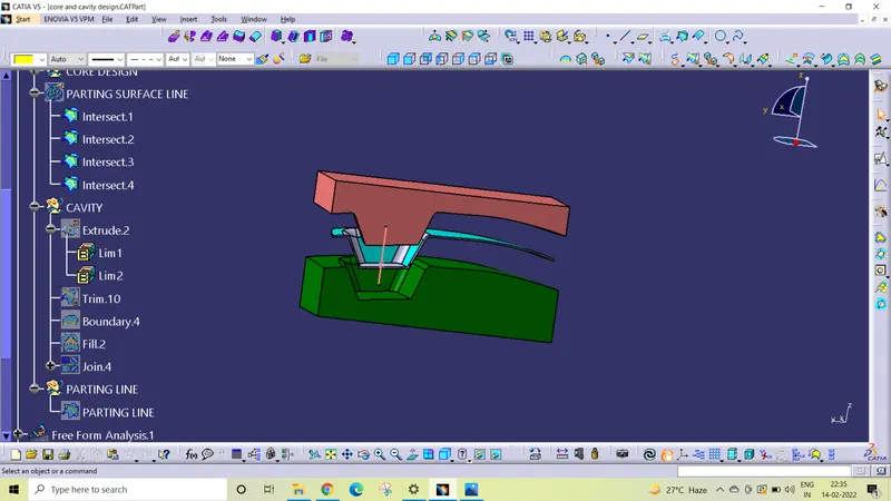
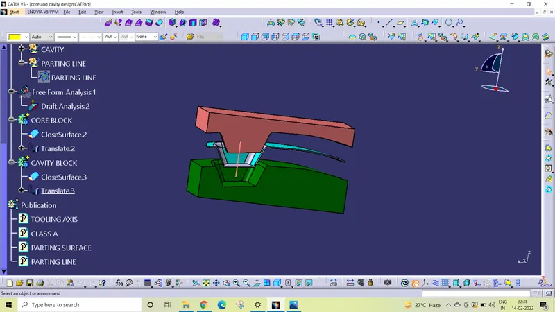
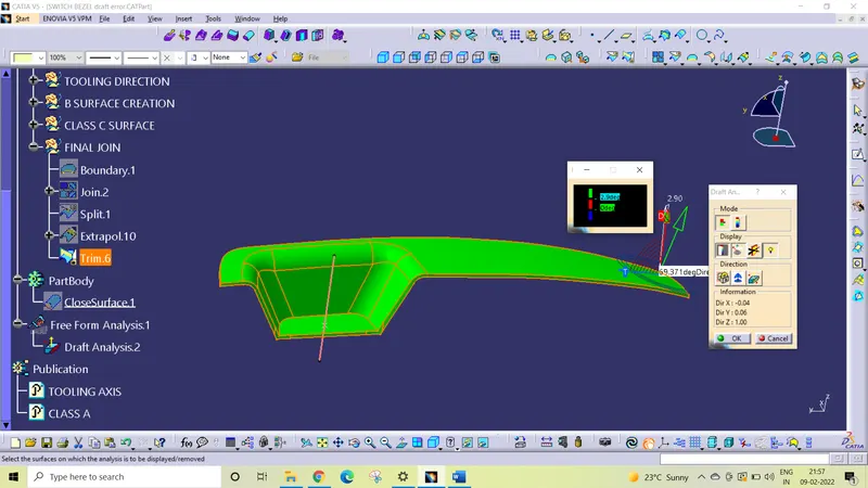
draft analysis
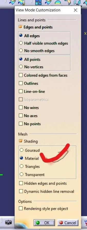
To perform the draft analysis on switch bezel model, first set the view parameters to material mode.
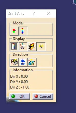
Then go to menu bar select insert analysis feature draft analysis
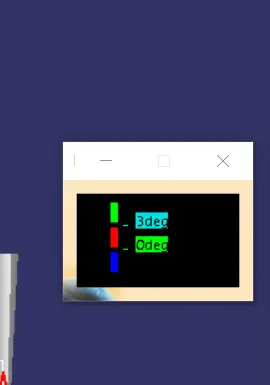
To give the draft direction, use compass and align Z axis of it with the final tooling axis for the switch bezel model. Once it is properly aligned, lock the draft direction. Select the switch bezel and it will show us the current draft angle of the model, set the draft value 2.9 degree under the color scale variant and press ok.
Using the draft analysis option we can perform draft analysis on Class A surface and final part of switch bezel .
Conclusion
The Core and cavity blocks for the switch bezel designed using Class A surface have been successfully created and draft analysis have also been performed for the same.