Week 8 - Challenge 5 - Core & Cavity Design
SWITCH BEZEL CONSTRUCTION
Creation of Tooling axis :
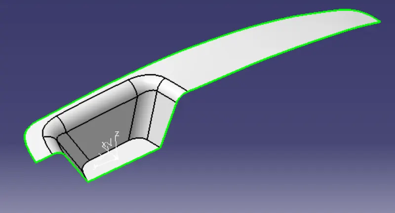
1) Initially start with creating a point on the surface and then axis system is created.
2) Now along the XY plane, intersection is created and then two lines are drawn using the two slopes.
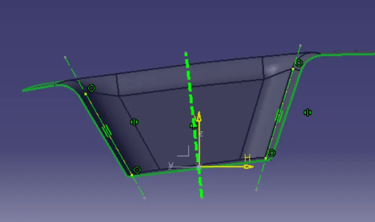
3) A bisecting line is created using them. Considering this as the tooling direction and draft analysis is performed.
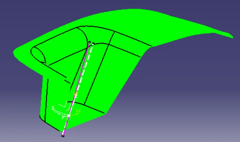
4) But all the faces are not cleared using that as the tool direction. Now rotate the created line along the x axis such that the rotated line can be used as the new tooling direction.
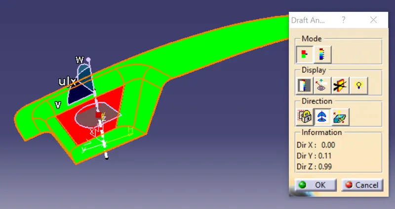
5) The line is rotated up to 3 degrees to make it clear all the faces. Now we can see all the faces are cleared by the tooling direction.
Class B, Class C surface and closebody creation :
1) Initially to simplify the class A surface, using UNTRIM option each surface is broken down to simple surfaces.
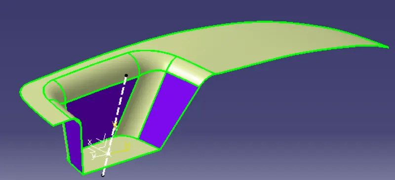
2)Now each of the surface is joined eliminating the edge fillets. So that offset surface can be performed without any errors. Extrapolate option is used to extend each surface and then trimmed together.
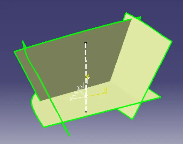
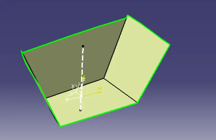
3) Finally the joined surface is offset to 2.5mm.Then edge fillet is applied on the offset surfaces by measuring the values from CLASS A surface.
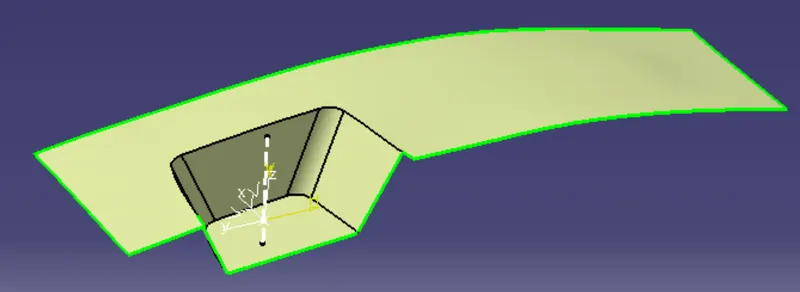
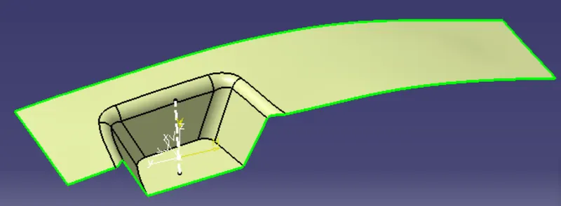
4) By using the SWEEP command the outer profile is selected , then by using tooling direction as the draft direction the CLASS C surface is created.Also a draft angle of 3 degrees is given to clear the faces.
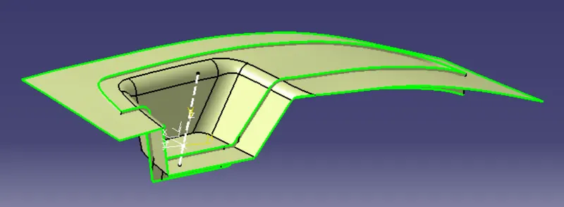
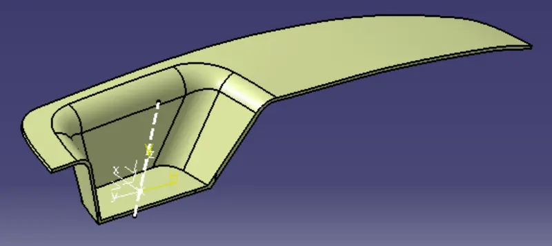
5) Now the offset surface, class c and the class A surface is trimmed together to form a closed body.
6) Then closebody option is used to form a solid body.
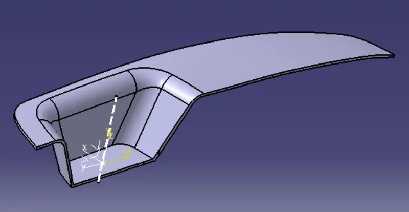
Draft analysis procedure:
1) Draft analysis is performed on the final solid body by choosing the compass and placing on the tooling axis we created.
2) Adjust the values on the colorscale to match your draft requirements.
3) Click the quick analysis tool and select your part so that the results are displayed. Check if all the faces are clearing the tool direction by identifying colors.
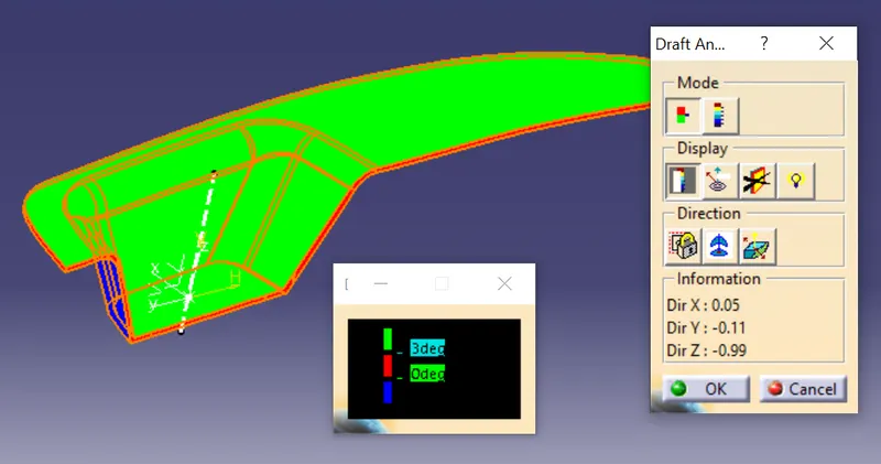
4) We can also use the analysis under running point to know the exact draft value on the surface by simply moving the cursor on the interested area.
5) As we can see all the surface when viewed from top/ tooling direction has only green and red color. The green and red color indicate a draft value between 0 to 3 degrees. So our surfaces satisfy the draft requirement and hence it is toolable.
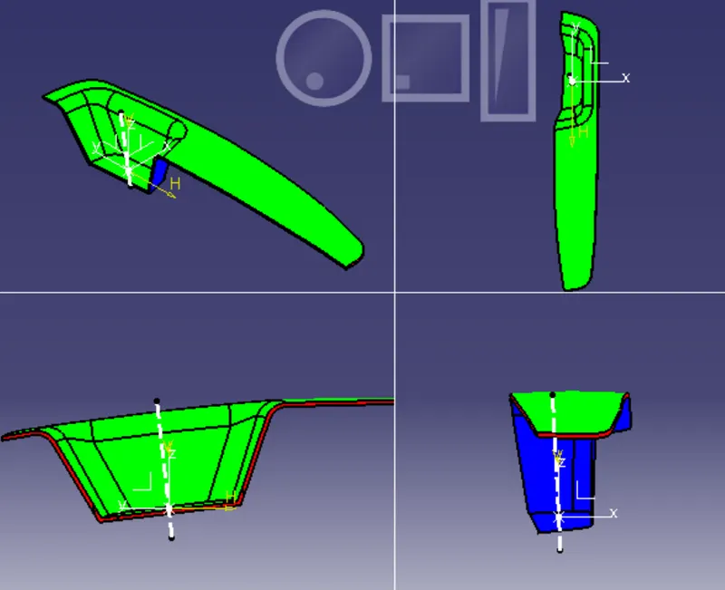
CORE AND CAVITY DESIGN
CORE DESIGN :
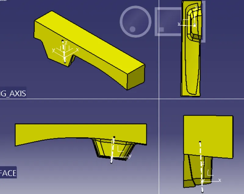
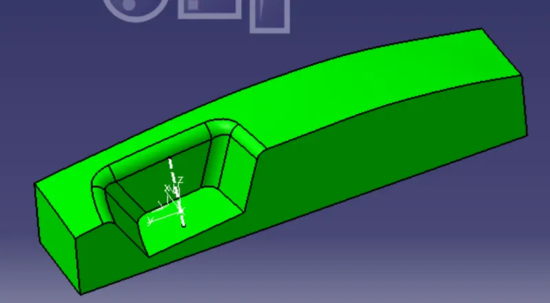
1) Initially the entire part (switch bezel) is analyzed to identify the core and cavity regions.
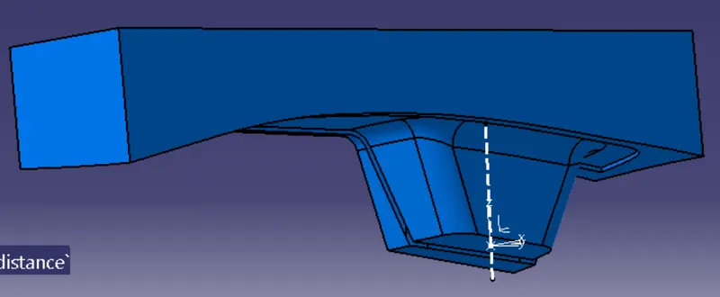
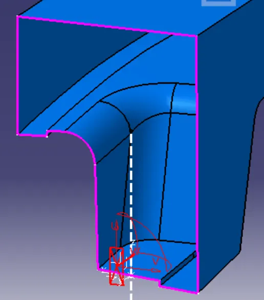
2) For the given switch bezel part , we need to clear the CLASS A and CLASS C surfaces with our core design.
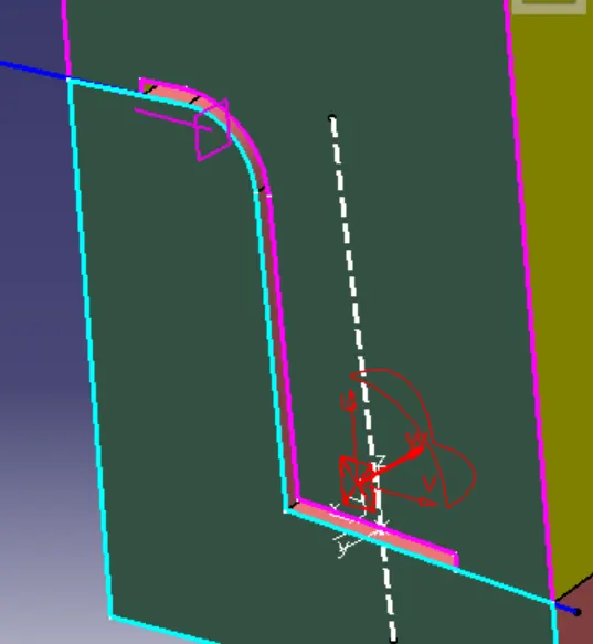
3) The parting line is placed on the class B surface to ensure that there is no issues on the visible CLASS A surface when mold is Injected.
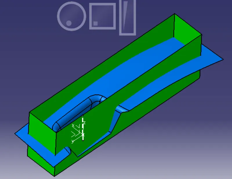
4) The surface which is in contact with the core and cavity of the mold is called as the parting surface.
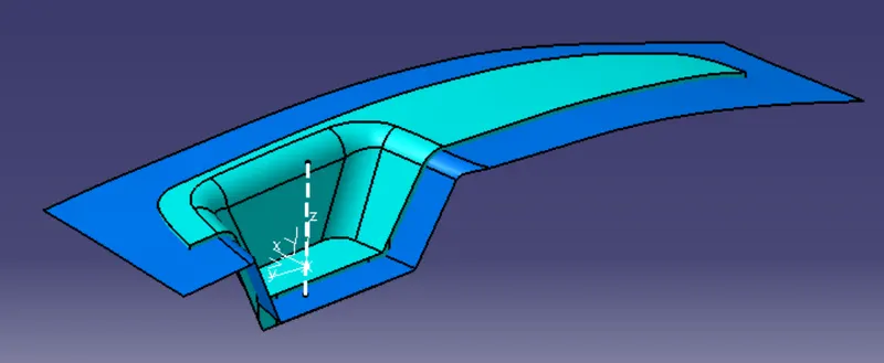
5) By extracting CLASS A and CLASS C , we need to trim it with the parting surface to get the core region.
PARTING SURFACE AND PARTING LINE :
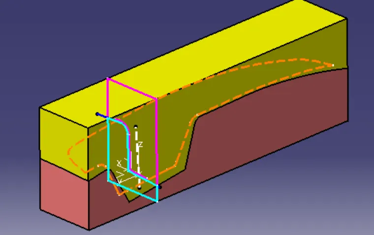
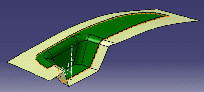
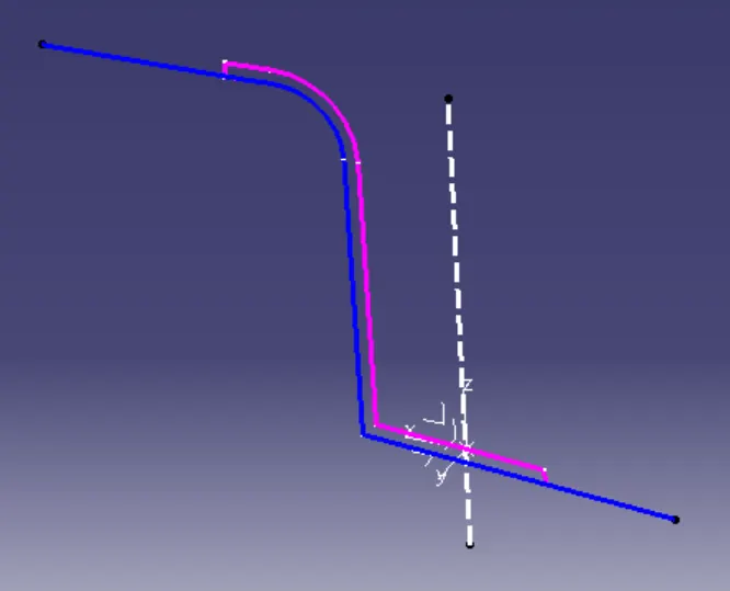
The parting surface is the one between the core and cavity region which splits them both.
The parting line is placed on the class B surface as shown.
CAVITY DESIGN :
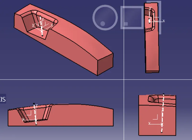
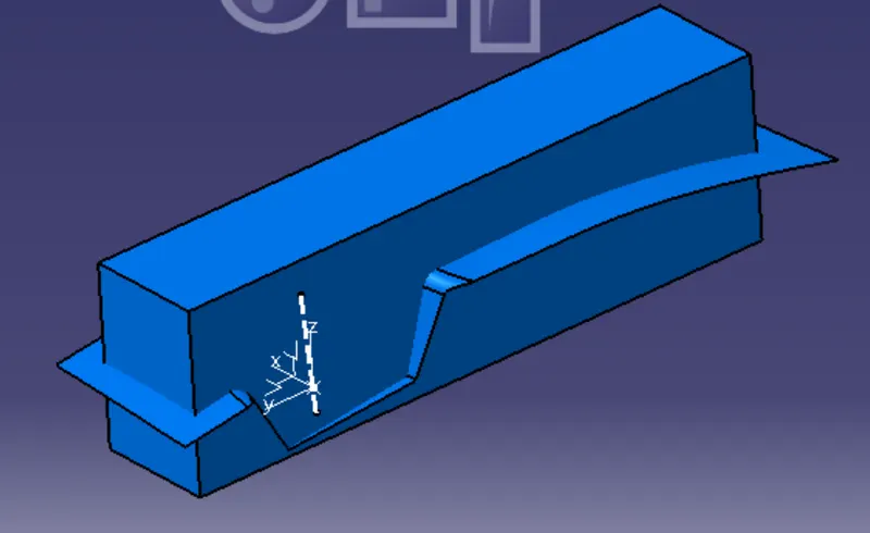
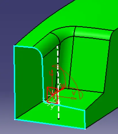
1) The cavity is formed by the extracting the CLASS B surface and creating a block with it.
2) The parting line is a part of the cavity surface and any defects like FLASH is reflected on the class b surface which needs to be cut off once the part is removed from mold.
3) The cavity mold has a dip or a depression as opposed to the core region which has a projection.
4) When two halves are joined a gap equivalent to the thickness of the component is formed where the molten plastic solidifies to form the final part.
VARIOUS VIEWS OF THE CORE AND CAVITY :