Week 8 - Challenge 5 - Core & Cavity Design
Report on the switch bezel: -
- In first step, we have to check the connectivity of the class-A surface. It means there should be no present gaps between two surfaces. It is fully connected class-A surface.
- The next step is to find a tooling axis of the class-A. It means there are so many features and slots are available in the feature because of that there are so many difficulties comes to find a proper tooling axis. Like - sliders, injector pins and so on.
- In next step we have to perform a operation with intersect tool. In this step X and Y direction, we have to check the improper lines and with that line using bisecting line command, we created a dummy tooling axis. But in this switch bezel in there is only three faces so we try a new method to find a tooling axis
- in this method we create a sketch in X and Y direction and create a dummy tooling axis and using both dummy tooling axis.
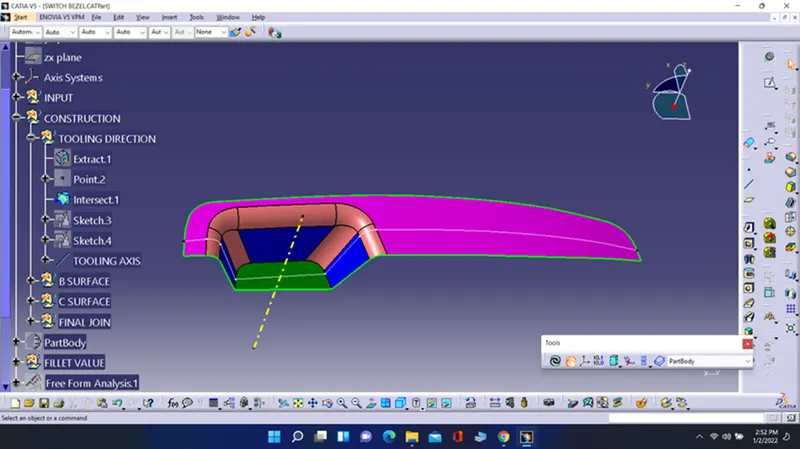
- Then using with these two line create a line with bisecting line and that is our tooling axis.
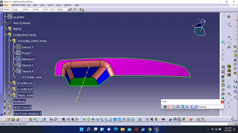
- Now name it as tooling axis. In next step we have to publication the class-A surface and tooling axis. This task is performed by the tool called as publication.
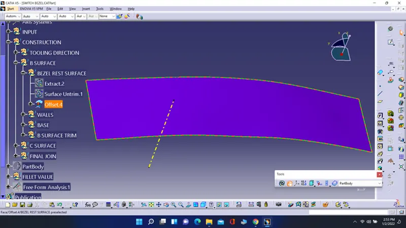
- Now for class B surface first go with the upper surface. For that extract the surfaces and then extrapolate them and then trim. In last offset them at a given distance. With this I created a upper face.
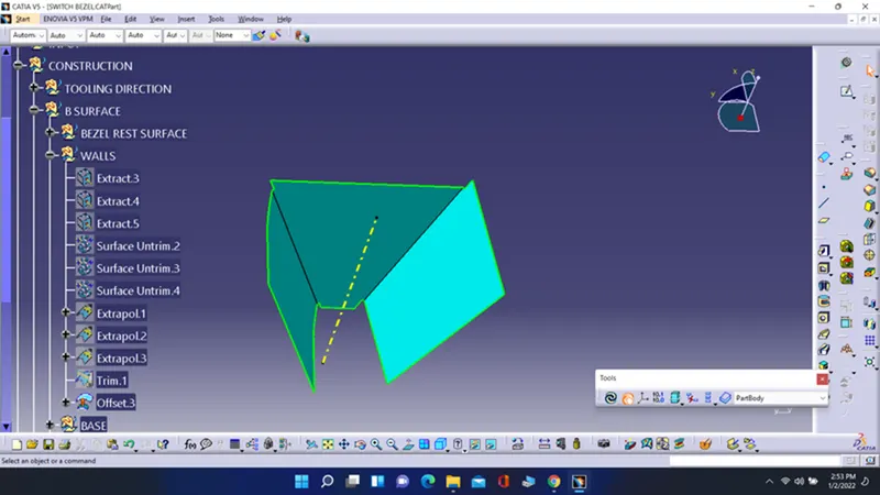
- Now follow same procedure and create a side faces and trim them with each other.
- Now for base surface follow the same procedure which is followed for the upper face. Like extract them then extrapolate then trim them with each other and in last offset them with given distance.
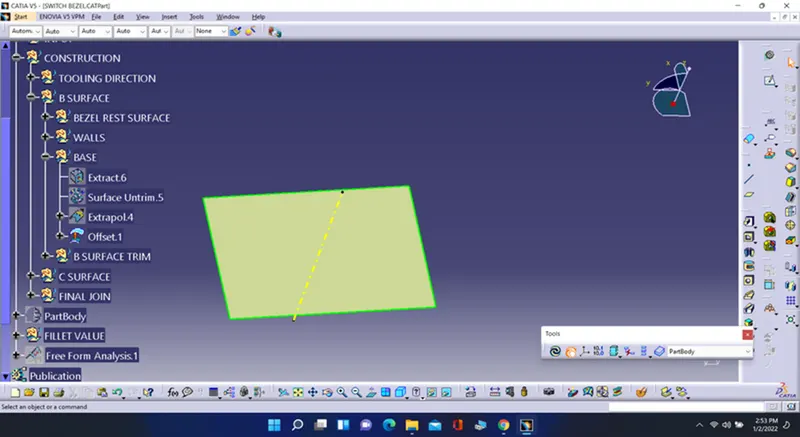
- Now trim the upper surface, side surfaces and base surface to create a class B surface.
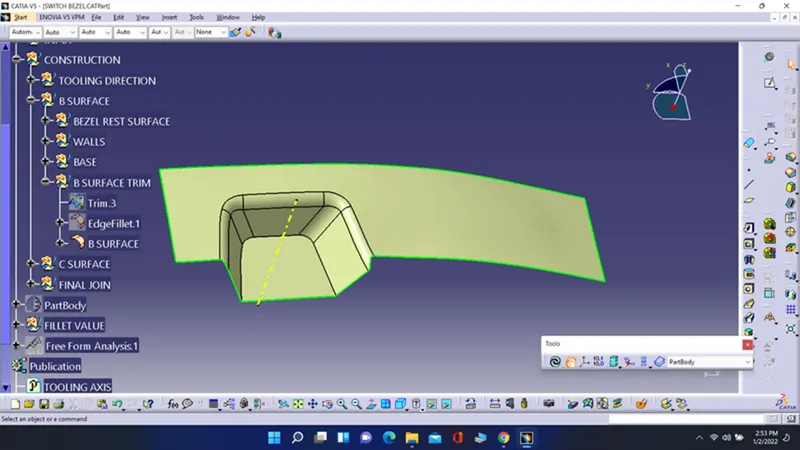
- Now for class C surface first create a boundary of the switch bezel surface but here create a boundary for half surface and then another half and swept it. Now use smooth curve command to create a smoothen curve and then extrapolate then to merge them with each other And now join the class A surface and all the swept surfaces to create a class C surface.
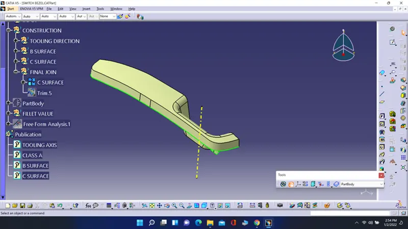
- Now trim the class B and class C surface with each other with proper side to create a final closed surface of the base bracket.
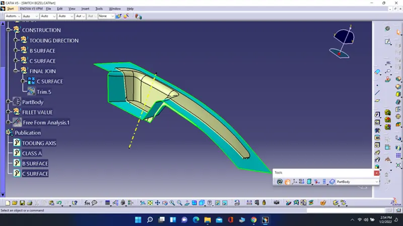
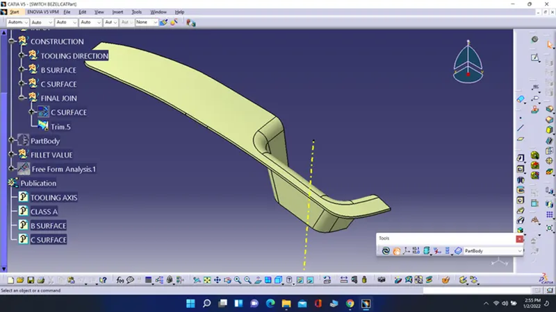
- To create a closed body go into a part body and then use a tool close surface and select the close surface and then enter.
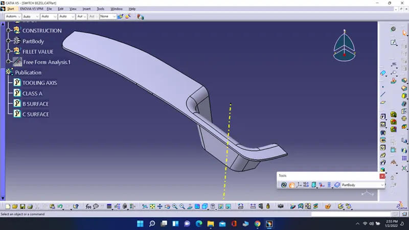
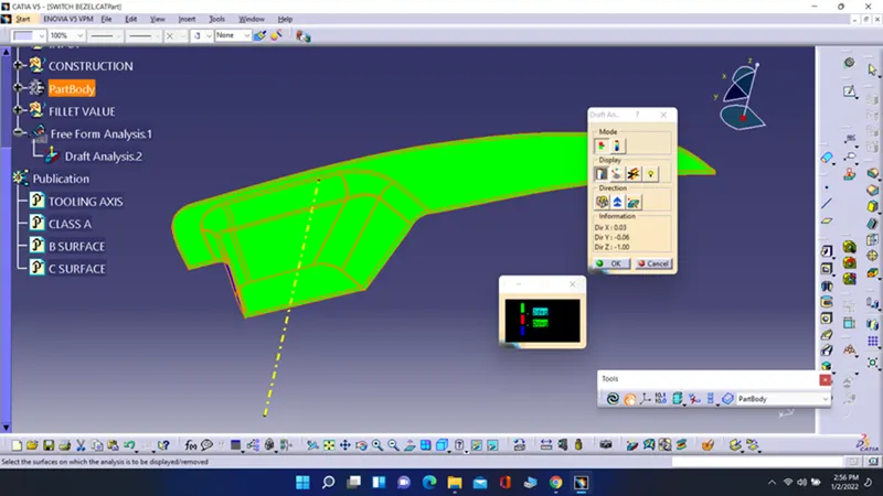
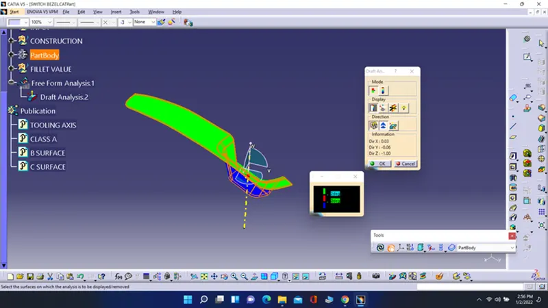
- Now we want to check the draft analysis on the part body. for that first go to the draft analysis tool and click on the compass sign and drag the compass sign holding a red point on to the tooling axis and put is as the W direction shows a upward direction. now click on lock sign to lock it. now click on the body it shows a green and red color.
- if it shows a blue color then click on the inverse sign which is on left side of compass sign.
- it shows a green sign on upper side with green colour and lower side with green color.
- you can check the draft angle with click on curser sign and drag it on where you want to check the angle.
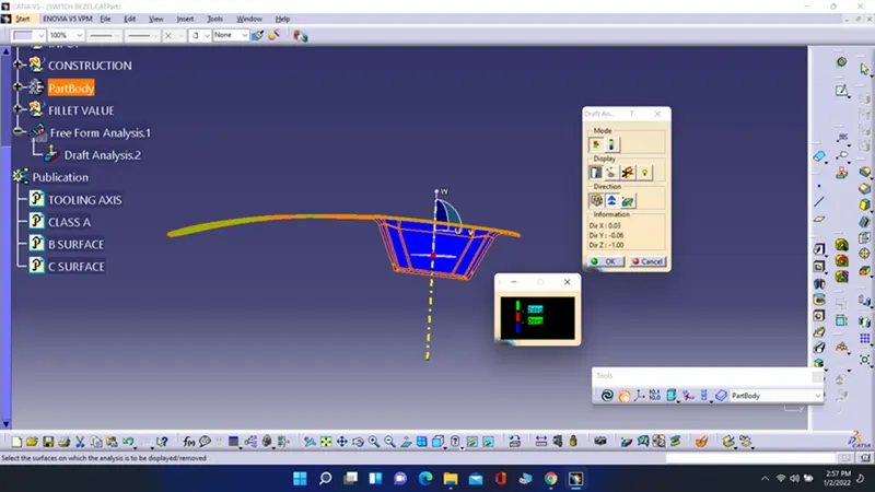
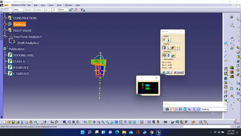
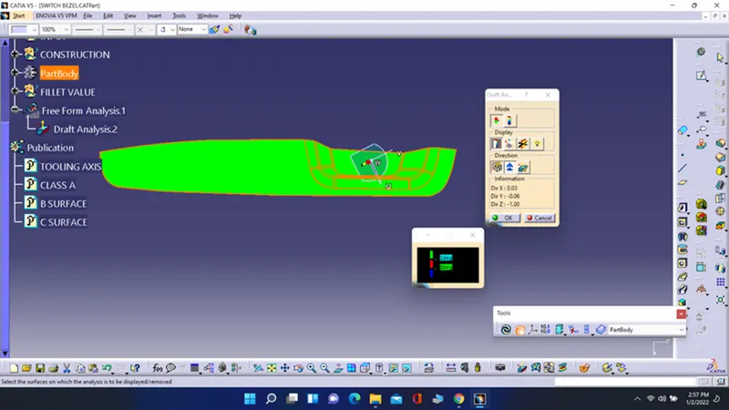
- Now for creating the core and cavity block for the switch bezel component first we want is parting line, parting surface then with use of them we can create a core and cavity surface then using closed surface command we can turn into a solid body.
- So first for creating a parting surface we want to choose a parting line which is the last edge of the component.
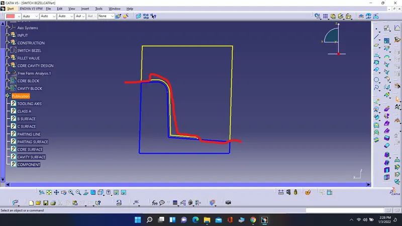
- Now select the class A surface and extrapolate it. Now trim this extrapolate surface with class C surface and then trim that surface with class B surface to get the output. This out put is our parting surface.
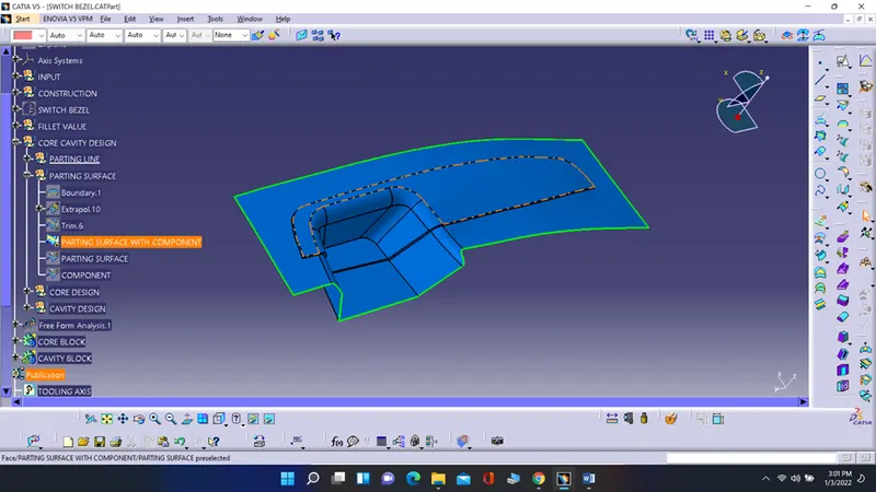
- But there is some correction is remaining in this which is the actual parting surface is only the outer surface from the component and the remaining is called as component.
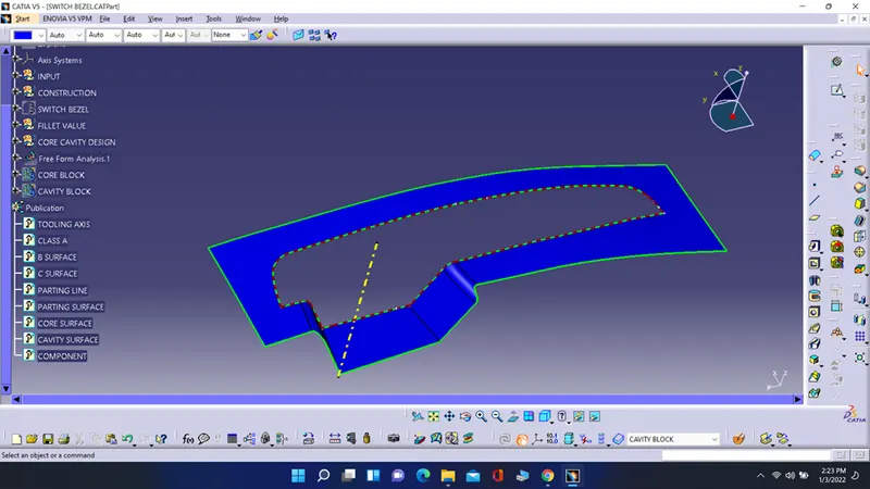
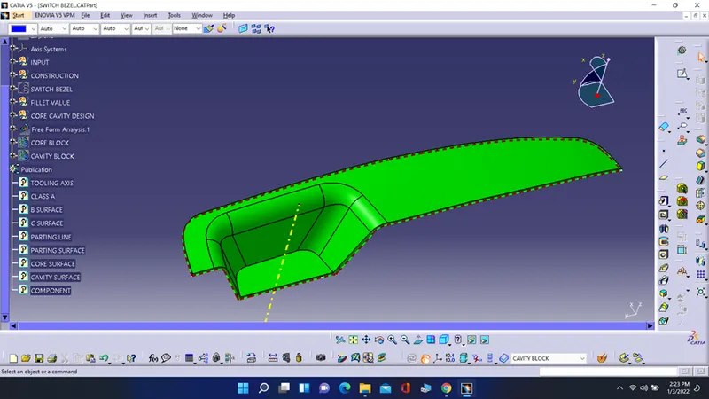
- Now for parting line use the intersect command and select the class C and class B surface which boundary you got is out parting line.
- Now publish the parting line and parting surface to easy use of them.
- Now for core surface create a rectangle which can cover whole component and then extrude is in tooling axis direction. Now trim this extrude surface with parting surface. Fill the blank face and join them and you got the core surface.
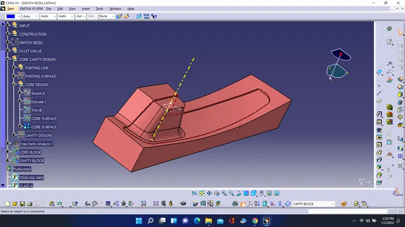
- Now for cavity surface select the class B surface and trim it with that extruded rectangular surface fill the blank face and you got a cavity surface.
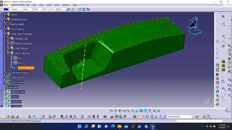
- Now go to a part design and use close surface command and turn the both core and cavity surfaces into a closed body.
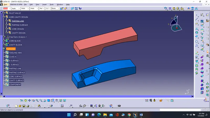
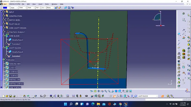
- Now translate them at some distance go check them. Take the cross section view also and check it.
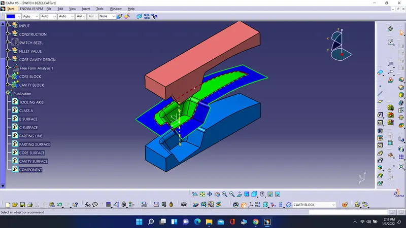
- This is how we can create a core and cavity block for the component.