Week 8 - Challenge 5 - Core & Cavity Design
OBJECTIVE:
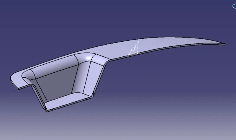
To create switch bezel component with the given class A surface and to create core and cavity blocks for the component.
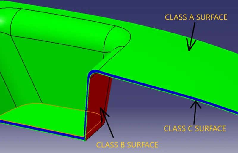
CLASS A SURFACE:
It is the outermost surface of the component with high accuracy and precision. It has aesthetic value and cannot be modified without authorization.
CLASS B SURFACE:
It is the inner surface of the component which we get after thickening it. The engineering features are attached to it.
CLASS C SURFACE:
It is the surface which joins the class A and class B surfaces along the boundaries.
SWITCH BEZEL DESIGN:
TOOLING AXIS CREATION:
Step 1: Check the boundary of the class A surface and ensure there is no gap in between the surface.
Step 2: Create an axis system on the class A surface by creating a point on it.
Step 3: Draw a sketch by intersecting class A surface with YZ plane and create tooling axis clearing along X direction by bisecting method.
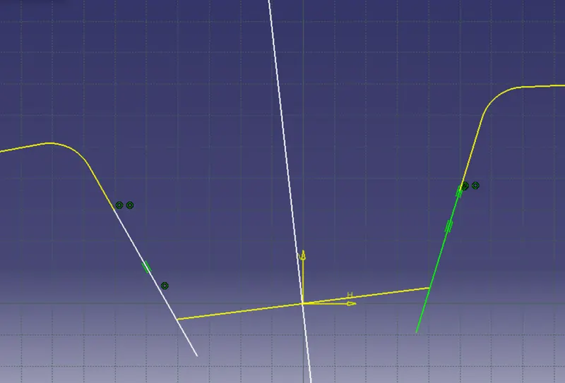
Step 4: Similarly, draw a sketch by intersecting class A surface with XZ plane and create tooling axis clearing along Y direction by creating an inclined line.
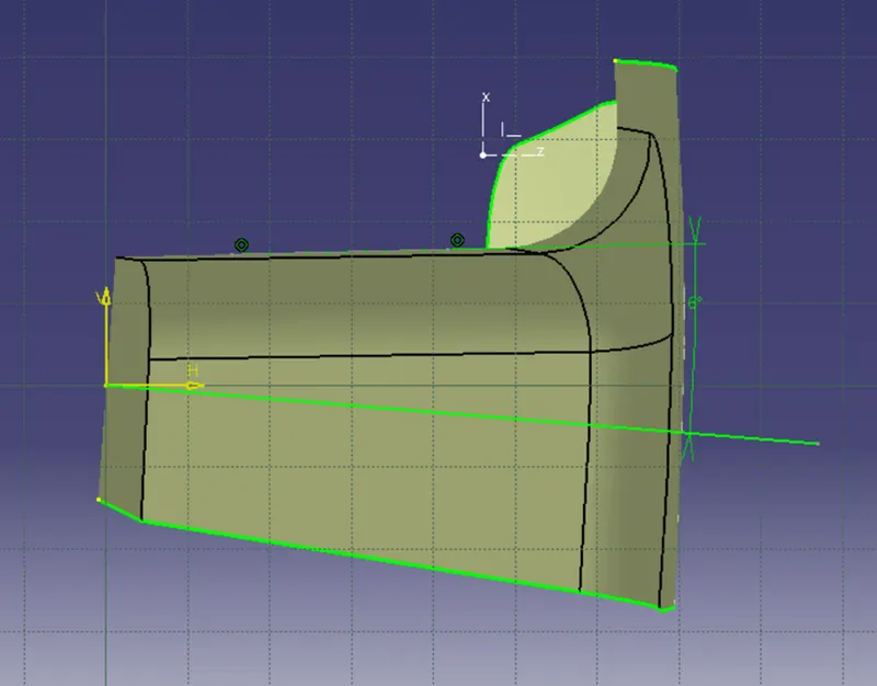
Step 5: Finally, create the tooling axis by bisecting the above two axes.
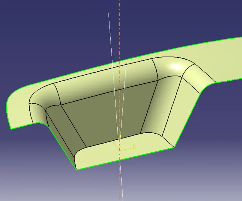
DRAFT ANALYSIS ON CLASS A SURFACE:
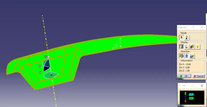
Step 1: Change the view to customized view and enable the material in shading option.
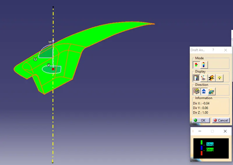
Step 2: Insert the feature draft analysis.
Step 3: Click the compass icon and place the compass along the tooling direction.
Step 4: Lock the draft direction and select the component to draft.
Step 5: Enable the color scale and change the draft value as required. Here 3 degree is given as draft angle.
Step 6: The green color indicates that the surface is more than 3 degree from the tooling direction. The blue color indicates that the surface is 0 to 3 degree from tooling direction. Red color indicates that the surface is less than 0 degree from tooling direction which indicates the negative draft.
CLASS B SURFACE:
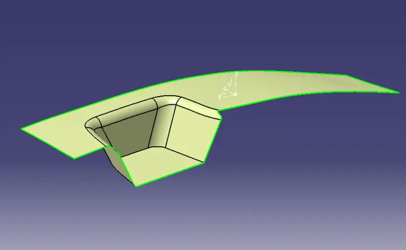
Step 1: Extract the individual surfaces from the class A surface.
Step 2: Untrim the extracted surfaces and extrapolate them as required.
Step 3: Offset the extrapolated surfaces downwards to get the thickness (2.5mm) of the component.
Step 4: Trim the offset surfaces and give fillets as required to get the class B surface with equal wall thickness.
CLASS C SURFACE:
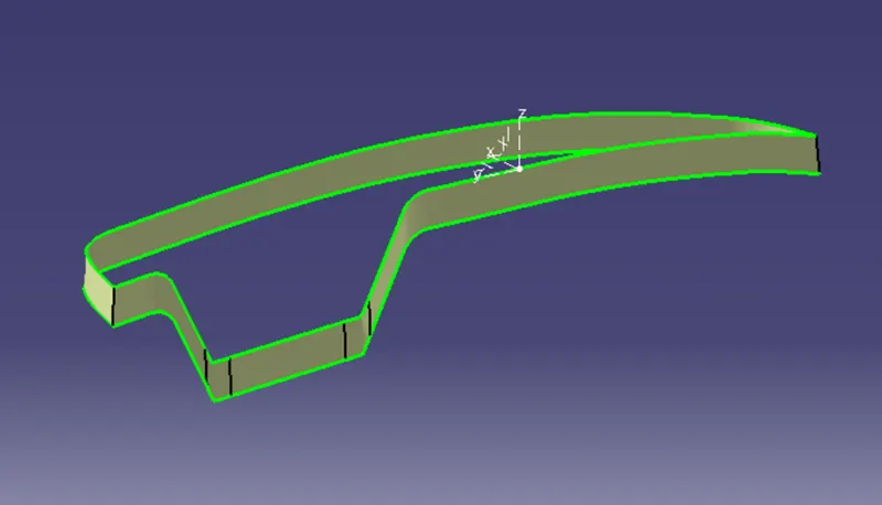
Step 1: Create the boundaries for the class A surface.
Step 2: Sweep the boundaries along the tooling direction with required draft angle to get the class C surface.
FINAL TRIM:
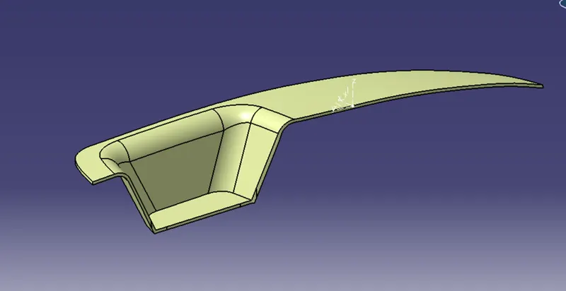
Finally trim class A, class B and class C surfaces to get the switch bezel surface and use closed surface feature to create a solid component. Then, perform draft analysis on the component.
CORE:
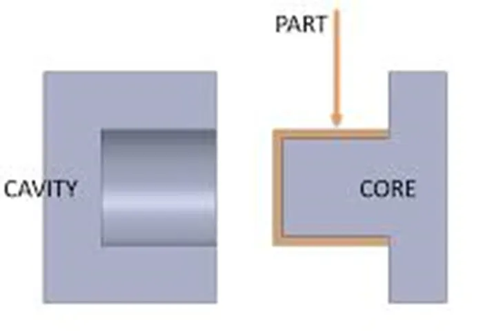
- Core is the male part which forms the internal shape of molding.
- In other words, Core is the mold side that forms the convex shaped space.
- Core is movable and closes the cavity.
CAVITY:
- Cavity is the female part which forms the external shape of molding.
- In other words, Cavity is the mold side that forms the concave shaped space
- Cavity mold is fixed.
PARTING SURFACE:
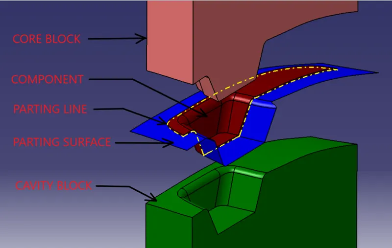
- The surface that splits the mold into two blocks namely core and cavity is called the parting surface.
- In other words, the intersecting surface between the core and cavity is called the parting surface.
- Flash will be created along this surface and removal of flash may affect the appearance of the final component. So, avoid creating the parting surface on class A surface side.
- It is the surface at which the core and cavity are held tightly at high pressure. So, create the parting surface as much as simple or flat to avoid the mismatch of core and cavity.
- Air vents are provided on this surface for ventilation.
PARTING LINE:
- The intersection of the parting surface and the component is called the parting line.
- In other words, it is the boundary of the parting surface.
- At this line, the draft angles change the direction.
CORE AND CAVITY DESIGN:
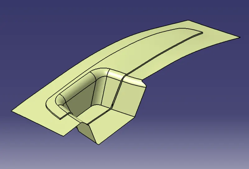
Step 1: Trim class A and class C surface and again trim it with class B surface as shown in the figure.
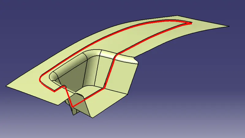
Step 2: Intersect class B and class C surface which represents the parting line.
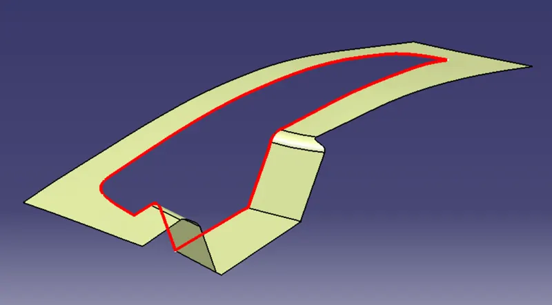
Step 3: Split the surface obtained in step 1 with the parting line to get the parting surface.
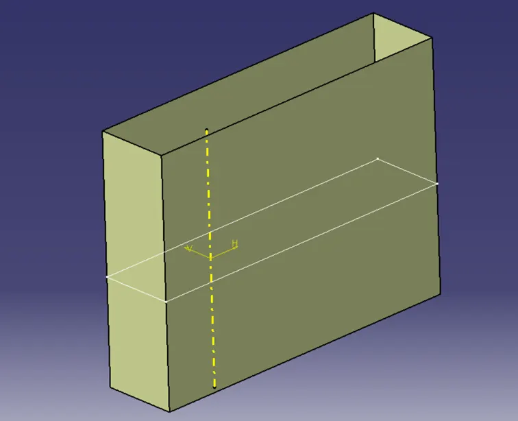
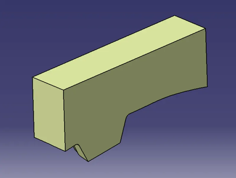
Step 4: Draw a rectangle in XY plane and extrude along the tooling direction.
Step 5: Trim this extrude with the surface obtained in step 1 and fill the top boundary to get the core block.
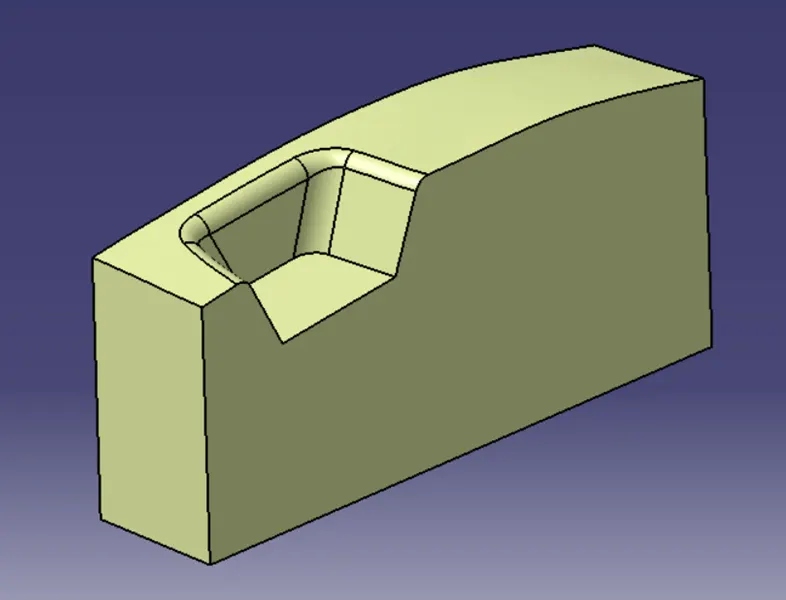
Step 6: Similarly, trim the extruded rectangle with class B surface to get the cavity block.
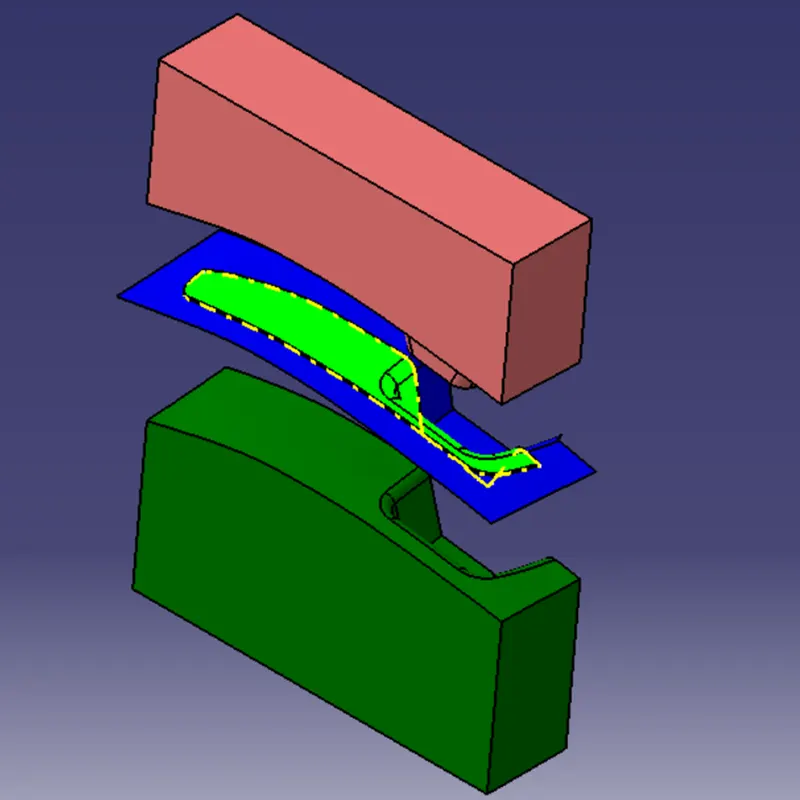
CORE & CAVITY BLOCKS IN DIFFERENT VIEWS:
ISOMETRIC VIEW:
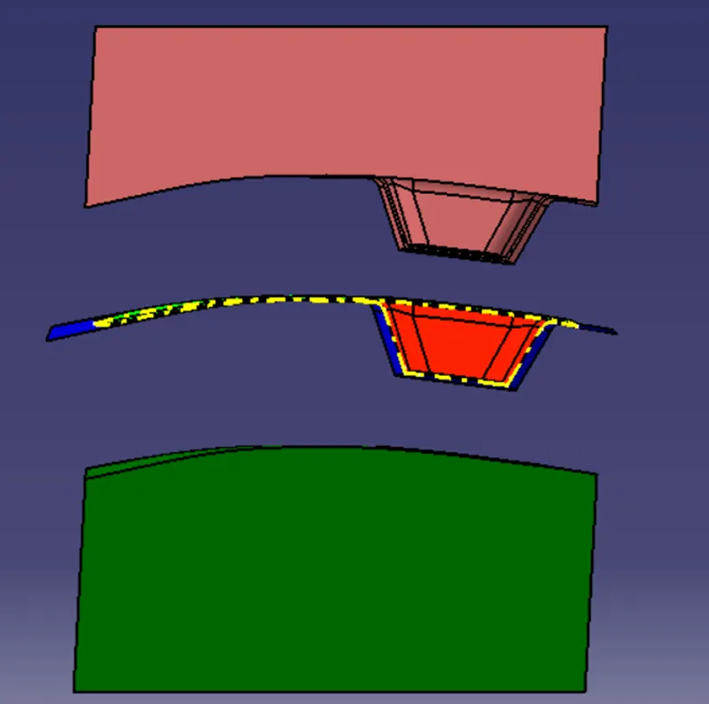
FRONT VIEW:
BACK VIEW:
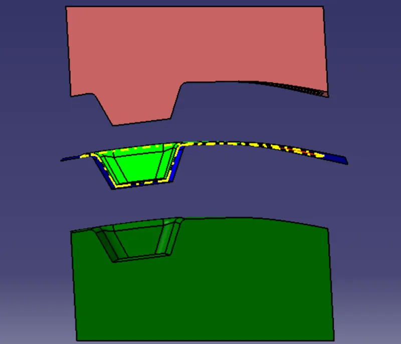
SIDE VIEW:
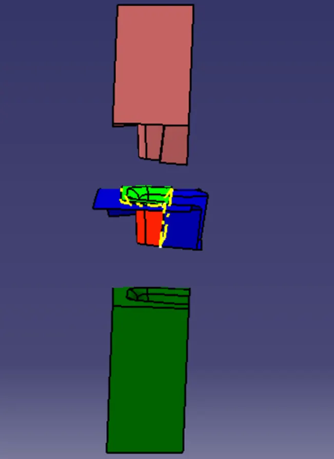
TOP VIEW:
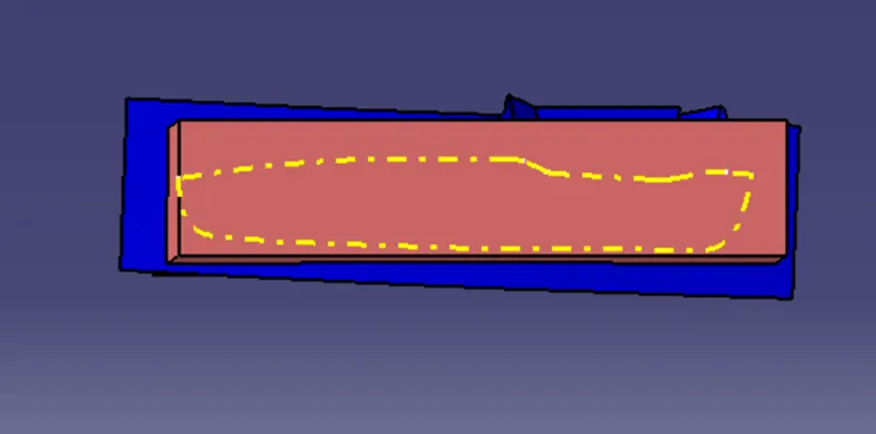
SECTION VIEW WITHOUT COMPONENT:
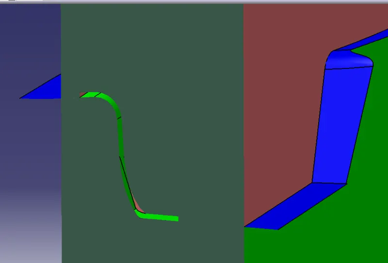
CONCLUSION:
Thus the switch bezel component is created and, core and cavity blocks are created for the component.