Week 8 - Challenge 5 - Core & Cavity Design
CORE AND CAVITY DESIGN
OBJECTIVE:
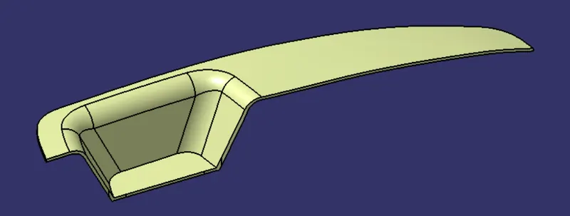
To design a core and cavity for a switch bezel plastic component.
SWITCH BEZEL:
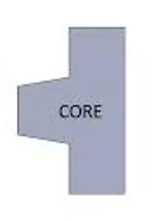
CORE:
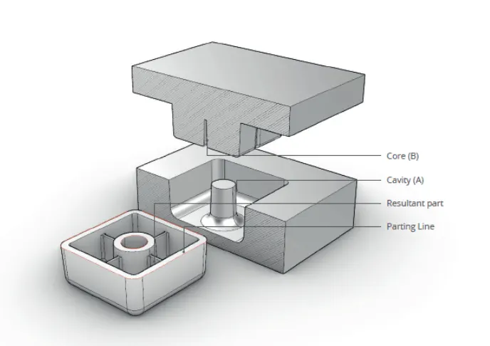
Core is the male part where it has the projection of the component.
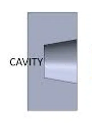
CAVITY:
Cavity is the female part where it has the depression of the component.
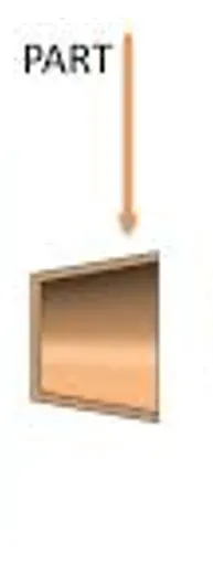
RESULTANT PART:
This is the part that is obtained from the respective core and cavity.
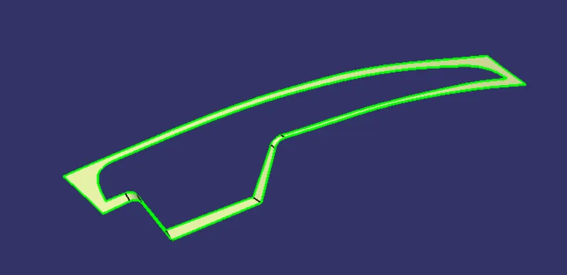
PARTING SURFACE:
Parting surface is the area where the core and cavity meets.
- The parting surface of a mould are those portions of both mould plates adjacent to the impression which seal together to form a sealand prevent the loss of plastic material from the impression.
- Parting surfaces are classified as flat and non-flat.
- The non-flat parting surfaces include stepped,profiled, and angled surfaces.
- If the parting surfaces are not properlymatched, the moulding material from theimpression will escape through the gap. This escaped melt is called flash.
- That is the reason why parting surface should always take place in class B surface and not in class A as when flash occurs it can be removed using hand tool by not affecting the class A aesthetically.
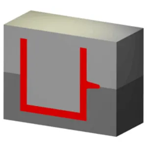
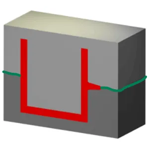
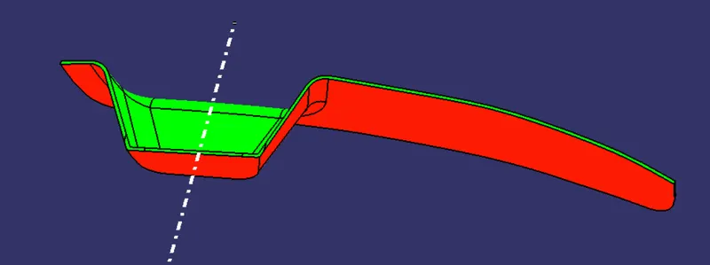
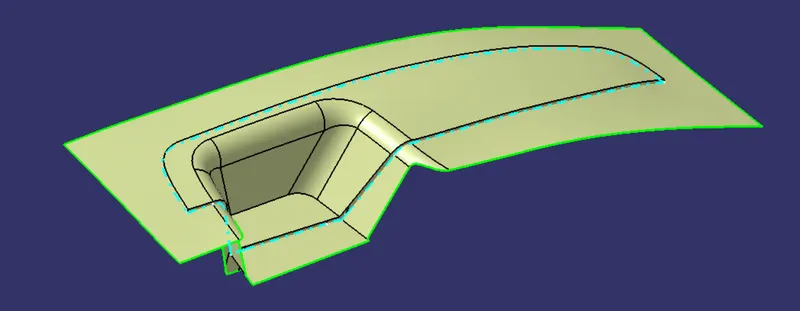
The area which is highlighted in green is called as the parting surface.
Types of Parting surface:
- Flat
- Angled
- Stepped
- Profile
PARTING LINE:
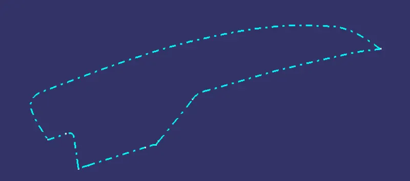
The intersection between the parting surface and the component is known as parting line.
CREATION OF CORE BLOCK:
The area which is highlighted in green takes place in the core block and the area which is red in colour takes place at the cavity block
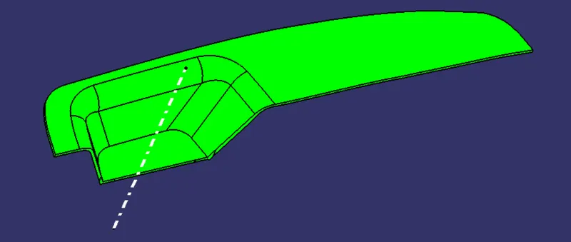
As we already have a B surface created,it is trimmed along with class A & C joined surface
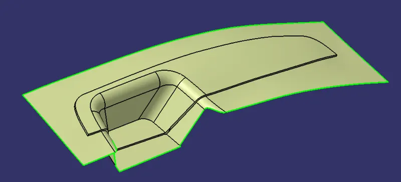
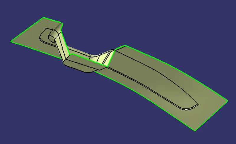
This surface is also called as parting surface with the component area.
Then the resultant surface is extrapolated and trimmed with an rectangular surface which is extruded along the tooling direction.
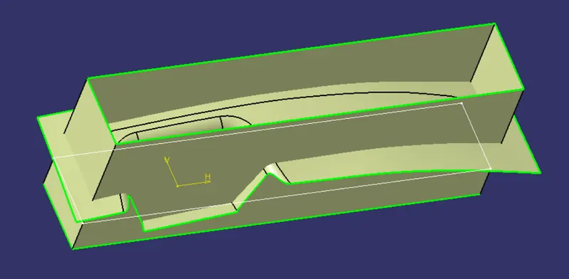
The top surface is then closed with the command Fill.
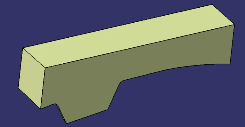
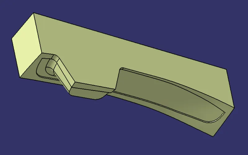
Now a closed surface is obtained and a solid body is created out of it.
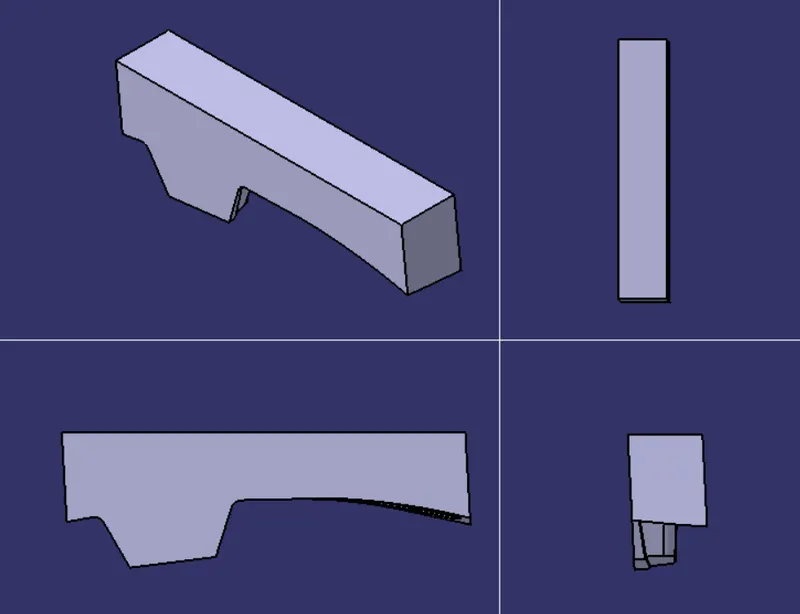
VARIOUS ORIENTATION OF THE CORE BLOCK:
PARTING SURFACE:
This is the parting surface with the component area itself.
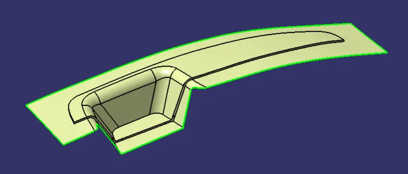
This is the original parting surface where the core and cavity exactly seal together.
CREATION OF CAVITY:
As aforementioned the area which is in red comes in the cavity block.
Here the class B surface is directly trimmed with the rectangular surface which is extruded along the tooling direction.
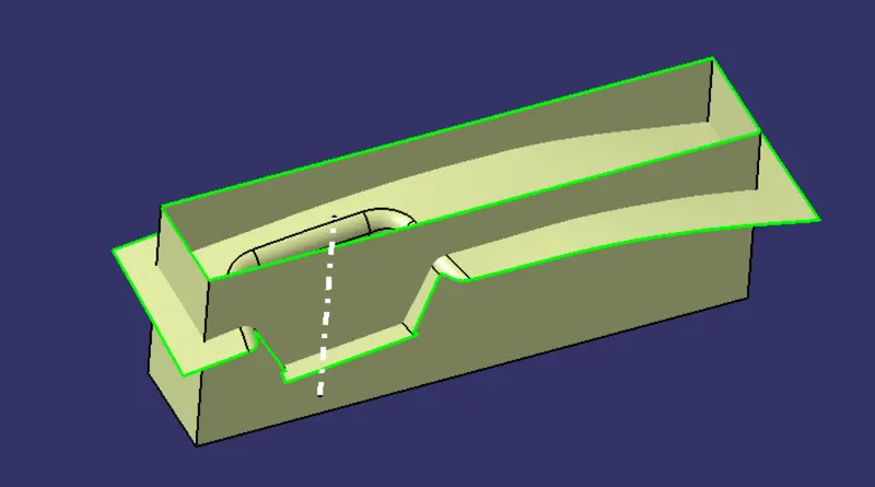
The bottom surface is closed using the fill command.
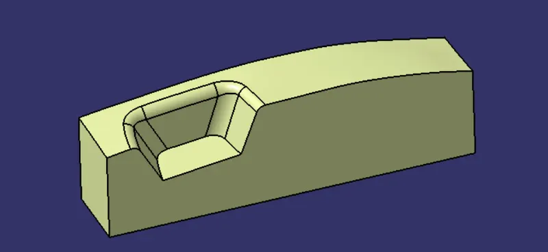
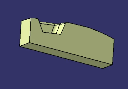
Now a closed surface is obtained and a solid body is created out of it.
VARIOUS ORIENTATION OF THE CAVITY BLOCK:
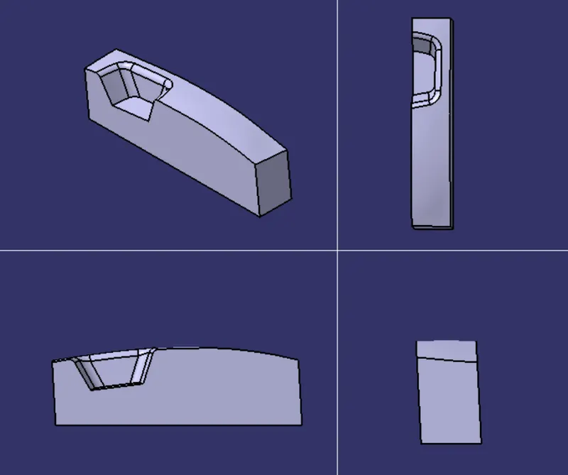
PARTING LINE:
The intersection between the class B surface and the final component is known as the parting line
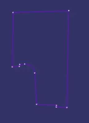
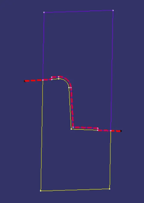
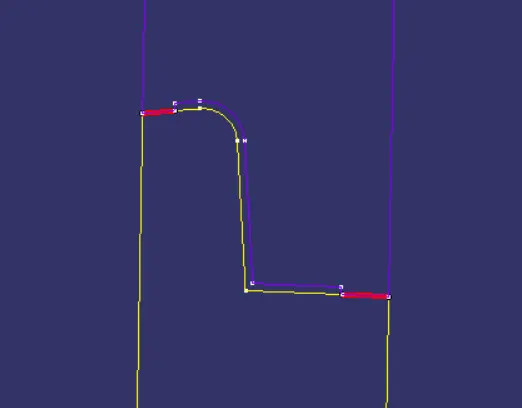
INTERSECTION ALONG XZ PLANE:
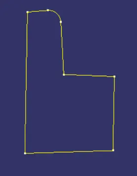
CORE CAVITY
The red dotted line is the parting surface w/ component area
The red line is the parting surface
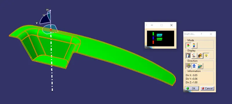
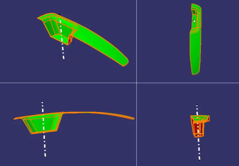
DRAFT ANALYSIS ON THE FINAL COMPONENT:
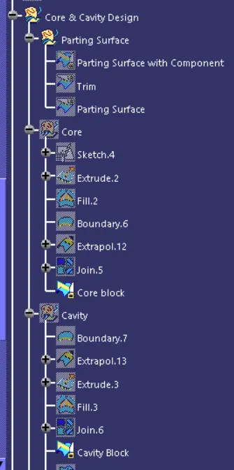
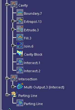
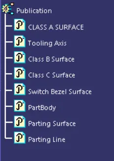
TREE STRUCTURE:
FINAL IMAGE OF THE CORE AND CAVITY WITH THE FINISHED COMPONENT:
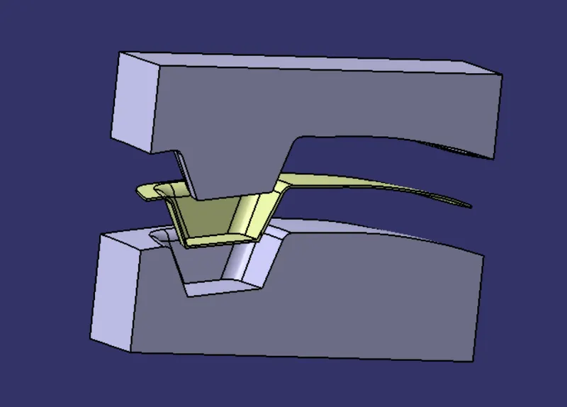

To conclude a core and cavity is designed for a switch bezel component.