Week 8 - Challenge 5 - Core & Cavity Design
AIM - To create the core and cavity block for the switch bezel.
PROCEDURE - The switch bezel that was created is shown below:
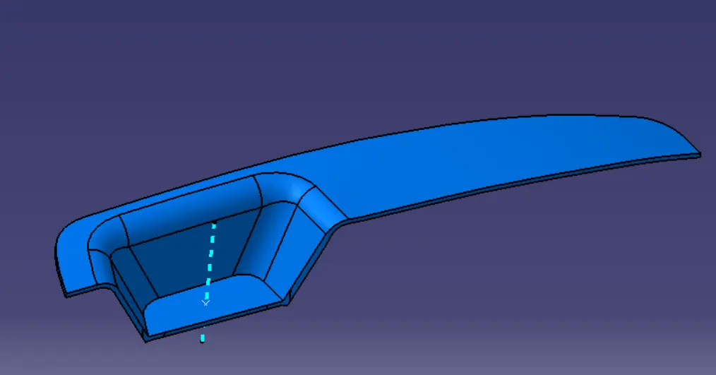
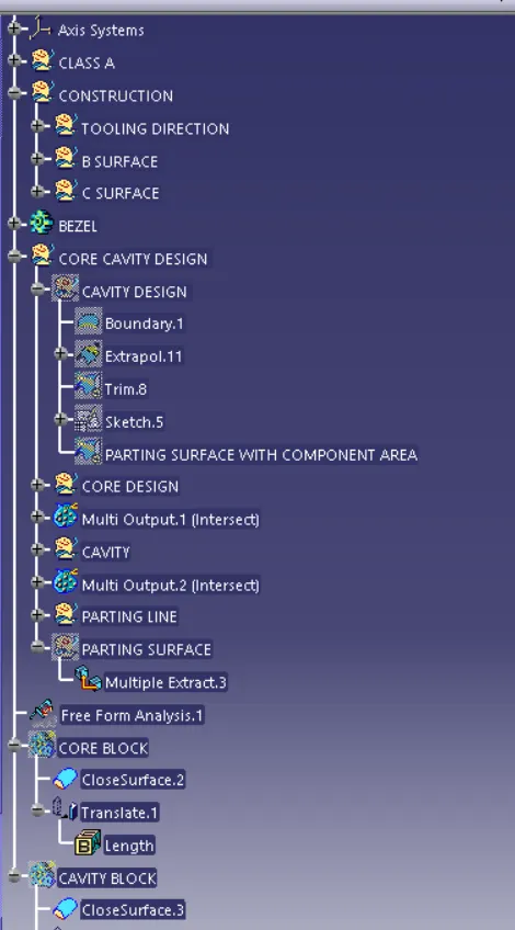
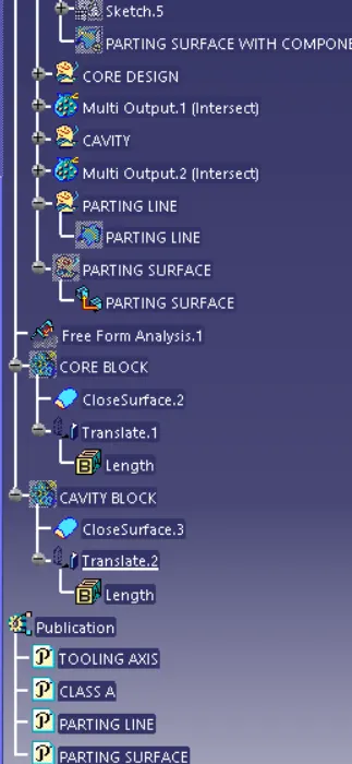
First, i will do the draft analysis of the model. For draft analysis, i need a tooling axis.
Tooling axis - The tooling axis is defined as the direction in which the mold opens or core and cavity opens and closes. The selection of the correct tooling axis is
important to ensure the component is taken out perfectly and also the cost of the component should be less.
I will start by inserting a geometrical set and naming it as a tooling direction. For creating the tooling axis i will analyze the model and see from which direction I
can see the whole model. So on analyzing the model I found out that the z-axis will be perfect for creating the tooling axis.Because along Z direction, only the
whole component is visible.
The tooling axis I have already created before the creation of the class B and Class C surface because I needed that tooling axis to give a draft on the C surface.
The tooling axis is shown above:
Then i will perform the draft analysis of the switch bezel model that i created.
Draft analysis - Draft analysis is a technique to analyze whether the component created is manufacturable or not based on the draft conditions applied. So here I
will provide the direction in which the component should be ejected to get the easy removal. My direction will be the tooling axis that I have created.
The minimum draft value for the Automotive plastic component is 3 degrees and those for the texture faces 7 degrees od draft is suitable. The draft is provided to
the component for easy removal from the mold in case of the plastic component.
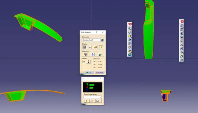
So here I will change the customize view parameters and will select the material mode.
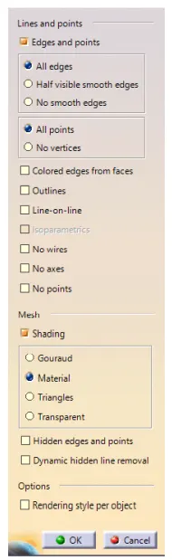
the section selects the color scale and turns on the light effect for proper visualization. then under the direction section, I will
click on the compass and will drag the compass from vehicle zero to my tooling axis. and then I will click on the lock feature and will select the class a surface. The
result is shown below:
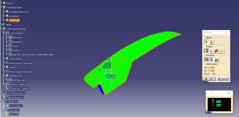
In the above fig. The Green color shows that the draft provided is more than 3.0 degrees
The Red color shows that the draft provided is between 0 and 3.0 degrees
The Blue color shows that the draft provided is negative.
And as i have already mentioned that minimum draft required for the plastic components is 3. so now i can say that my model is manufacturable.
After doing the draft analysis will design the core and cavity block for the switch bezel.
I will start by inserting a geometrical set and naming it as Core and Cavity design. Inside it first, i will create the parting surface.
Parting surface - Designed for the removal of the plastic product and the cold slug, the parting surface is where the core meets the cavity, and usually locates at
the largest section of a product. usually, parting surfaces are the biggest projection outline of the part.
When designing a plastic injection mold, the selection of the parting surface is an important design factor. With a reasonable parting surface selection, the mold
structure can be simpler, making it easier to mold and release the plastic product, with product quality guaranteed. If the parting surface is inappropriately
selected, mold structure becomes complex, making it difficult to mold the plastic product, thus affecting product quality. Therefore, the selection of the parting
surface is of great importance to the design of mold structure.
Design parting surface should follow the following principles:
1. Design the injection mold structure as simple as possible. Avoid or reduce side parting as much as possible to reduce the complexity of mold making.
2. Ease of de-molding. As far as possible, for instance, the plastic parts should stay in a fixed halve of the injection mold and ejected by the ejection system,
avoid side de-molding action.
3. Ensure the dimensional accuracy of the molded parts. Try to make the parts with similar dimensional accuracy requirements in the same module to reduce
manufacturing and assembly errors.
4. Ensure appearance requirement of the molded parts. Flash or mismatch occurs usually on parting surfaces, so the parting surface should not be designed
on any high-quality requirement surfaces.
5. Ensure adequate venting. If possible, the parting surface should be placed at the end of the mold flow. This is going to be a good advantage of filling and
venting.
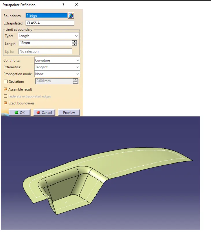
Now for creating the parting surface I will first extrapolate the class A surface. The extrapolation parameters are shown below
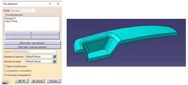
Then i will the extrapolated class A surface with the class C surface. The trim parameters are shown below
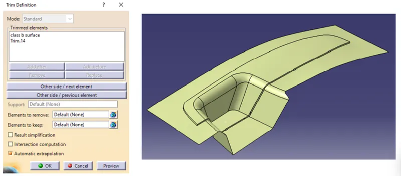
Then I will trim the result of the above trim with class B surface to get a parting surface with the component area. The trim is shown below:
Parting line - A parting line, in the industrial casting of molds, is the borderline in which draft angles change direction. That is, it is the dividing line that splits the
core and cavity halves of a molded part. It is sometimes a starting point for the mold parting surface. or in other words, the parting line is the junction between the
core half and cavity half and the parting surface.
So here for creating the parting line I will intersect the join of Class A and Class C surface with Class B surface that will be my parting line.
The intersection parameters and the parting line is shown below:
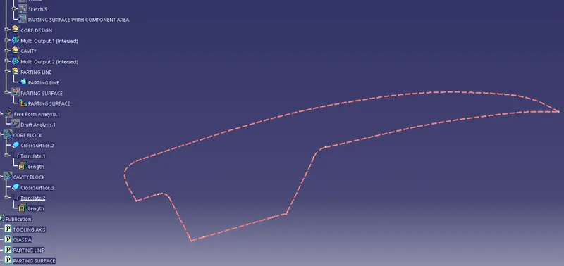
Now for creating the actual parting surface because the parting surface is whatever surface is there outside the component. so for this, i will split the parting
surface with the component area with the parting line. The split result which will be my paring surface is shown below:
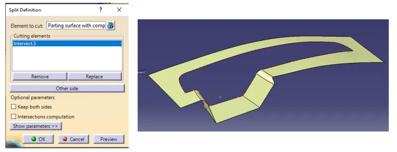
After creating this I will create a core block.
Core - Cores are normally designed on the moving half of the mold base. This is the ejection side. On this side of the mold, there is the ejection system of the
injection molding machine. This system connects to the ejector system of the mold. The core has the projection.
For the core block, I will create a sketch on the axis system that I created. In that sketch, I will create one rectangle. The sketch is shown below:
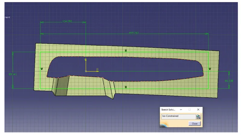
I will create the solid part from the surface using the close surface feature in part design. The solid core block is shown below:
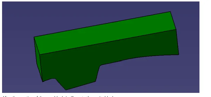
cavity - Cavities are normally designed in the fixed half of the mold base, the injection site. Sometimes, however, cavities may be mounted on the moving side.
The cavity has depression. Cavities are normally the "nice side" of the plastic part: well finished, without marks.
For the cavity creation, I will trim the extrude that I created with the class b surface. The trim is shown below
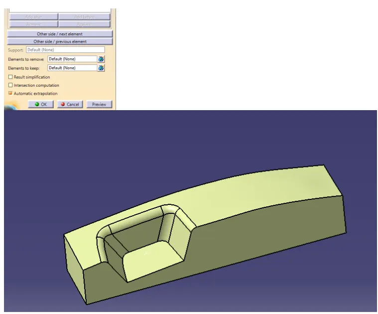
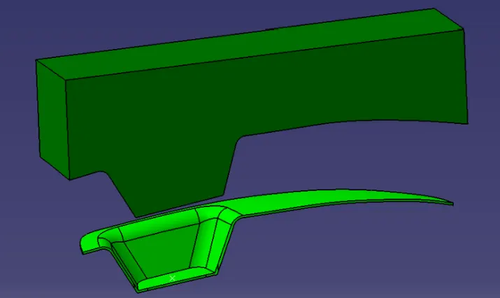
The translation of the cavity will be in a lower direction and it is shown below
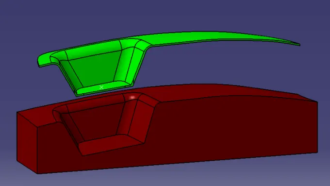
For better visualization, i have created the intersection between the elements. The intersection parameters are shown below:
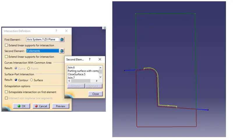
n the above-shown figure The yellow color part is the component that is the switch bezel.
The Maroon color part is the cavity
The Green color part is the core
The Blue color part is the parting surface.
The plastic material will be injected and it will occupy the space between the core and cavity and the component will be formed.
RESULT - The draft analysis on the switch bezel is done and core and cavity block is also created and shown below:
1) The draft analysis on the switch bezel
ONCLUSION - This concludes the creation of a core and cavity block for the switch bezel.