Week 8 - Challenge 5 - Core & Cavity Design
Title- Week 8 - Challenge 5 - Core & Cavity Design
Aim- Create the Core and cavity blocks for the switch bezel designed in the earlier challenge.
Objectives-
1. To understand core & cavity in mold design
2. To understand importance of parting surface & parting line
3. Create core & cavity for the switch bezel part
Core and Cavity-
In a typical injection molding machine, one half of the mold (the A-side) is attached to the fixed side of the press, and the other half of the mold (the B-side) is attached to the moving clamp side of the press. The clamp (or B) side contains the ejection actuator, which controls the ejector pins. The clamp forces the A and B-sides together, molten plastic is injected into the mold and allowed to cool, the clamp pulls the B-side of the mold away, the ejection pins are actuated, and the part releases from the mold.
Let's use a mold for a plastic drinking glass as an example. To ensure that the part stays in the mold half with the ejector system, we would design the mold so that the outside of the glass is formed in the cavity of the mold (A-side) and the inside would be formed by the core of the mold (B-Side). As the plastic cools, the part would shrink away from the A-side of the mold and shrink onto the core in the B-side. As the mold opens, the glass will release from the A-Side, and stay in the B-side, where it can be pushed off from the core by the ejector system.
If the mold design were reversed, the outside of the glass would shrink away from the cavity in the B-side and onto the core in the A-Side. The glass would release from the B-side and stick to the A-side where there are no ejector pins. At this point, we have a serious problem.
A Rectangular Example-
Let's consider a rectangular enclosure with four through holes. The outside of the enclosure will be a cavity in the A-side of the mold and the inside will be a core on the B-side. Design for the holes, however, could be handled in two different ways: They could be drafted toward the A-side, requiring cores in the A-side of the mold, but this might cause the part to stick to the A-side of the mold. A better approach would be to draft the cores to the B-side, ensuring that the part would stick to the B-side of the mold. Similarly, any tab or strip sticking from the part or spanning an internal hole should be drafted to the B-side to prevent sticking in the A-side and bending or tearing off when the mold opens. And, of course, the design should also avoid heavy texture on the outside of a part without adequate draft, as this could cause the part to stick in the A-Side.
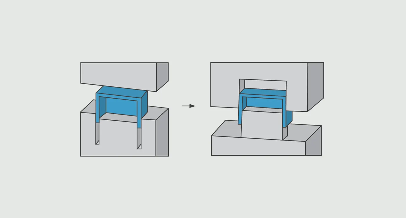
Parting surface-
Generally, injection mold has two major components: the movable halves and the fixed halve, during injection molding process, these two halves are pressed tightly and form a sealed hollow to avoid the melt flow leakage and maintain certain holding pressure, the pressed surface are called parting surface, usually parting surface are the biggest projection outline of the part.
Types of parting surface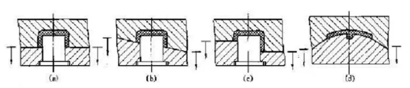
Flat parting surface (see figure a)
Parting surface tilt (see figure b)
Stepped parting surface (see figure c)
Curved parting surface (see figure d)
Parting surface design principles-
Parting surface design directly affects the product quality, ease of construction and operation of the injection mold, the mold design is one of the key factors to success.
Design parting surface should follow the following principles:
- Design the injection mold structure as simple as possible. Avoid or reduce side parting as much as possible to reduce the complexity of mold making.
- Ease of de-molding. As far as possible, for instance, the plastic parts should stay in fixed halve of the injection mold and ejected by ejection system, avoid side de-molding action.
- Ensure the dimensional accuracy of the molded parts. Try to make the parts with similar dimensional accuracy requirements in the same module to reduce manufacturing and assembly errors.
- Ensure appearance requirement of the molded parts. Flash or mismatch occurs usually on parting surface, so the parting surface should not be designed on any high-quality requirement surfaces.
- Ensure adequate venting. If possible, parting surface should be place at the end of the mold flow. This is going to be a good advantage of filling and venting.
Selecting a parting line is an important part when designing plastic injection molds. The parting line is the basic element for mold design and manufacturing. A reasonably selected parting line makes the mold manufacturing process easier and quality of plastic parts higher. Otherwise, it will bring trouble to mold making.
In order to remove the plastic part from the mold, and to load the movable core or inserts into the mold body, the mold must be divided into two or more parts. Generally, the mold structure is roughly divided into two main parts: fixed half and moving half. When the mold body is closed, the contact surface of the cavity and core plates makes a parting line.
Usually, the parting line of the mold is perpendicular to the mold opening direction of the injection molding machine. When opening the mold, eject or remove the cooled and solidified plastic parts from the mold (or automatically drop), and then remove the debris in the mold cavity, or place the insert to movable core in the mold cavity. The picture shows the basic form of the parting line. The mold opens from A. The fixed half of mold is not moved and the moving half moves and separates. Usually, we call the parting line of the moving and fixed molds the main parting line.
However, sometimes the structures of mold require it to be parted several times from several directions, which is the case of multi-step parting. The following are the basic forms of multi-step parting.
In the below figure, in order to take out the condensed material at the point gate, the mold is first parted from A. After the condensed material is pulled off and taken out, the part is parted from B to eject and be removed.
In the below figure, the mold is first parted from A. Then under the action of the ejector, the mold opens from B, and the plastic part is removed.
According to the sequence of the parting, the letters A and B are used at the parting lines.
Parting line
The form of parting line depends on the specific situation of the plastic part, but generally there are several types: vertical stepped, inclined, curved and integrated parting lines.
1. Vertical parting line
The vertical parting line is commonly used. It is a plane perpendicular to the mold opening direction, as shown in the below figure.
2. Stepped parting line
According to the specific situation of some plastic parts, the parting line is made stepped, as shown in the below figure.
For the stepped parting line, due to the large force on one side of the cavity, the injection eccentric force is generated on both sides of the cavity, which causes the relative sliding tendency between the fixed half and the moving half molds. Its sliding direction is shown in the below figure.
If this unbalanced eccentric force is small, a guide pin can be used to support it. But if the eccentric force is too large, it will cause excessive wear of the guide pin and the guide bush, cause the decline in the quality of the plastic part. To compensate for the shortcoming, the following solutions can be used.
(1). Set a wedge-shaped insert on one side of the cavity, as shown in the below figure. In this way, the eccentric force of the injection can be offset, the relative position between the cavity and the core can be maintained, and it can be easily changed when worn.
(2). Arrange the two mold cavities to be symmetrical, as shown in below 2 figures. Make the injection forces received on both sides of the mold body balanced, and make the mold structure compact. The use of side gates is also very beneficial to the flow of part materials.
3. Beveled parting line
As in the below figure, the shape of the parting line is beveled.
4. Curved parting line
As in the below figure, the shape of the parting line is curved.
5. Comprehensive parting line
This form is based on the needs of the structure of the plastic part, sometimes combining steeped and curved parting lines, or beveled and curved parting line to form a comprehensive parting line, as shown in the below figure.
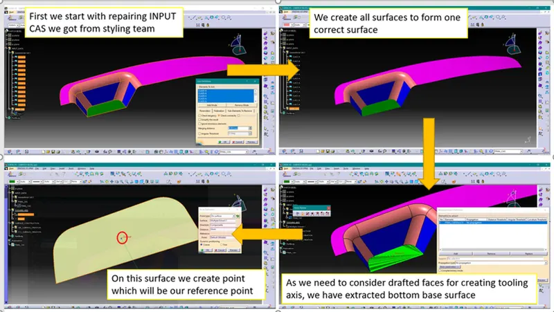
Creation of Tooling Axis by Bisecting method-
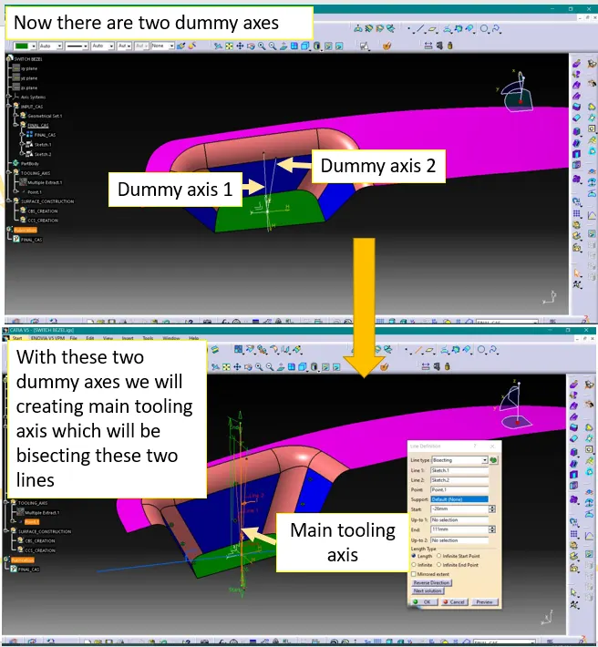
1. Creation of Dummy Tooling Axis
To create Tooling Axis first we have to create Dummy Tooling Axis.
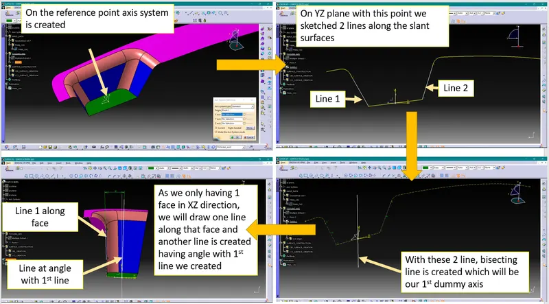
Note- Line we created with angle of 3deg primarily. If with 3deg draft analysis will found ok we will keep it, otherwise we will increase the angle so that all the surfaces will clear draft analysis.
2. Creating main tooling axis
Draft Analysis-
Process of performing draft analysis in Catia V5-
1. Click on the draft analysis icon ( ) or go to Insert>Analysis>Feature Draft Analysis
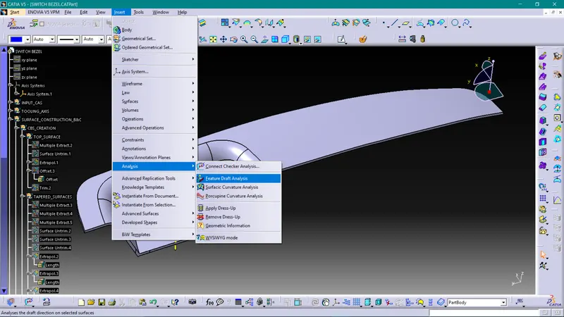
Note- While doing Draft analysis make sure you are enabling material view mode.
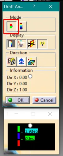
2. Switch on quick analysis mode by clicking on below highlighted icon
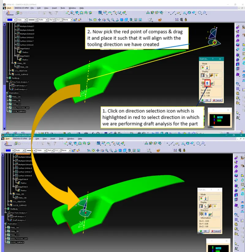
3. Selecting Draft Direction
4. Selecting surface
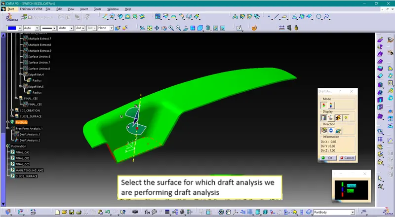
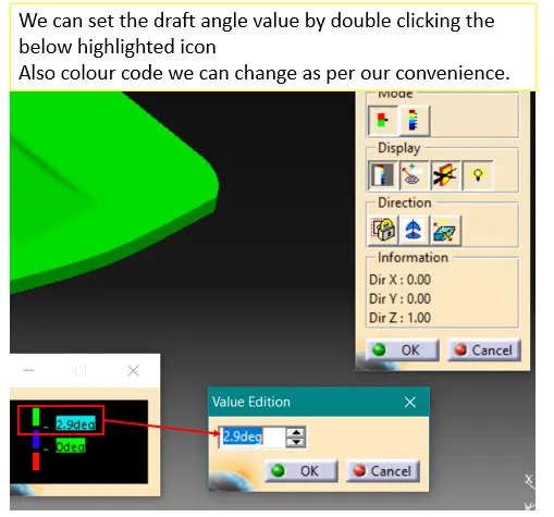
5. Input the draft angles
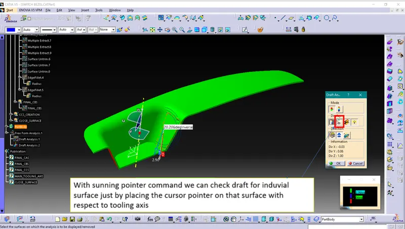
6. Running point
Draft analysis for CAS-
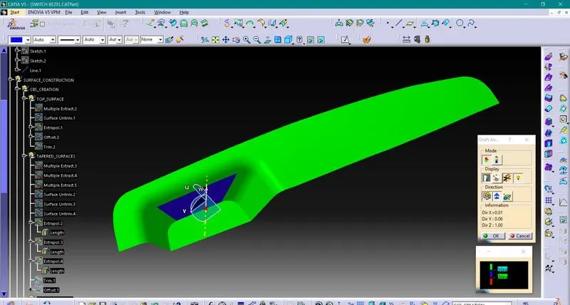
As we have discussed earlier regarding angle in creation 2nd dummy tooling direction, with 3deg inclination our surfaces are not clearing in draft analysis. So, we have increased inclination to 5deg.
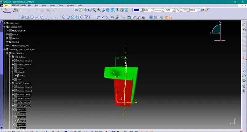
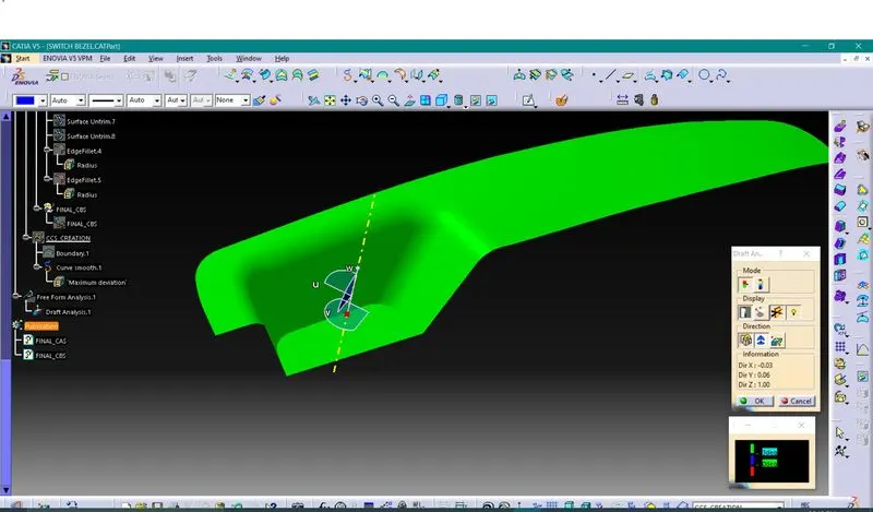
With 5deg inclination our drafted surfaces are clearing draft analysis
Draft analysis for Solid part-
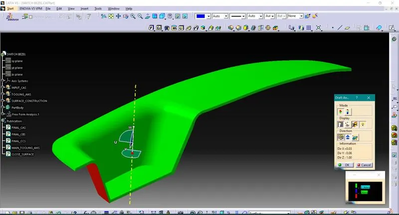
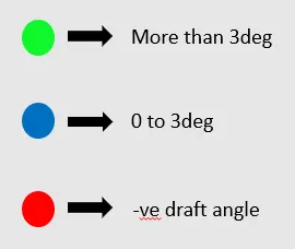
Solid model with the proper color code of the draft angle in various orientations (Isometric, Front, Side, and Top View)-
Creation of Core Cavity Blocks for the switch bezel-
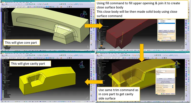
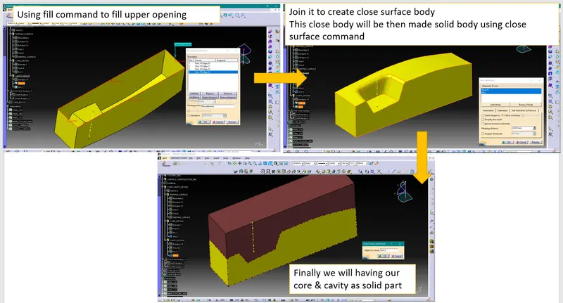
As we have already done draft analysis, this part is clearing draft analysis. So, we will be creating core & cavity considering main tooling axis.
Process of creating core & cavity is explained below-
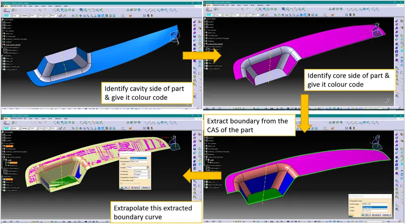
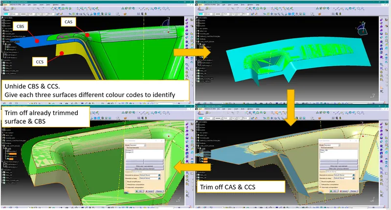
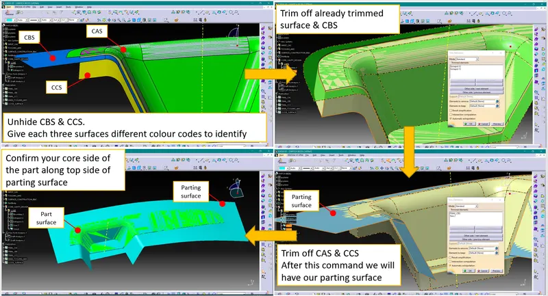
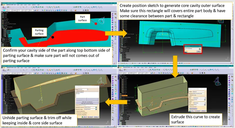
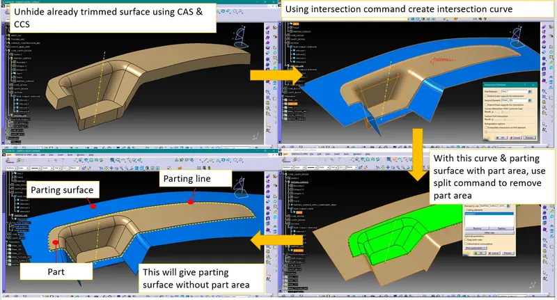
Creation of parting surface with & without part area-
1. Parting surface with part area-
2. Parting surface without part area-
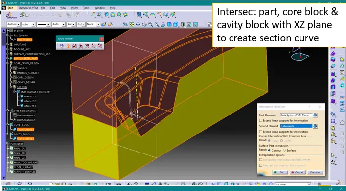
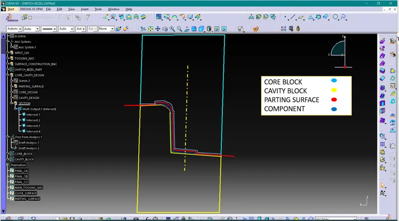
Section view-
By taking section of part, core block & cavity block together we can have better understanding of our design.
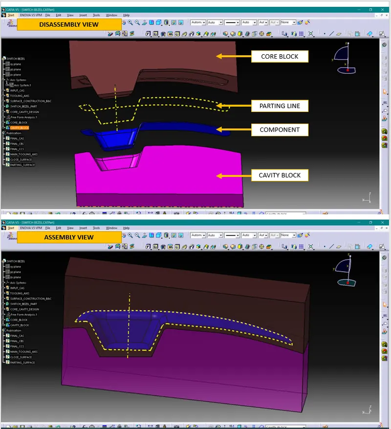
Assembly & disassembly view-
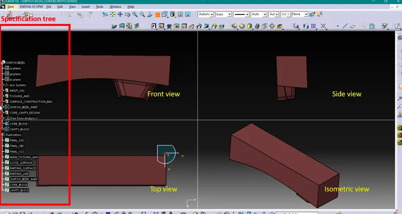
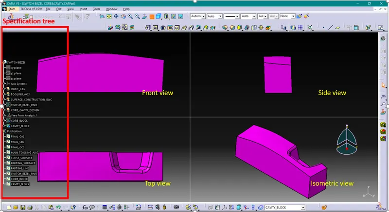
Core and cavity blocks in various orientations-
Core block view
Cavity block view
Conclusion-
1. We have understood core & cavity in mold design
2. We have understood importance of parting surface & parting line
3. We have core & cavity for the switch bezel part