Week 8 - Challenge 5 - Core & Cavity Design
AIM:
Design the core and cavity of the SWITCH BEZEL.
SOFTWARE USED: CATIA V5
DRAFTING ANALYSIS:
The draft analysis command enables you to detect if the part your DRAFTED will be easy to removed.this type of ANALYSIS is performed based on color ranges identifying zones on the analyzed element where the deviation from the DRAFT direction in at any point,corresponds to specific values.
PARTING SURFACE:
Parting surface is a surface which acts as a connect between CORE & CAVITY.
A parting surface is a surface in the model that you designate to split a workpiece, die block, or another volume. A parting surface is made up of a set of features, with the first feature called the base quilt. Any additional features that you create using operations such as trim, merge, and extend are called patches.
PARTING LINE:
Parting line is the intresection between parting surface and the component thatss were the CORE & CAVITY have split each other.
The parting line of a die cast component represents where the two different sides of the mold come together. This line often (but not always) marks the border between the inside and outside of the part.
DESIGN PARTING SURFACE SHOULD FOLLOW THE FOLLOWING PRINCIPLES:
1.Design the enjection mold simplee as possible.AVOID OR REDUCE side parting as much as possible to reduce complexity of the mold making.
2.Ease of de-molding as far as possible,for instance the plastic parts should stay in fixed halve of injection mold and should ejected by ejection system avoid side de-molding action.
3.ensure the dimension accuracy of the mold parts,try to make the parts similar dimension accuracy requirements in the same mold to reduce manufacturing and assembly errors.
4.Ensure the apperance requirement of molded parts,finish or mismatch usually occurs on panting surface should not be designed on high quality requirement surfaces.
5.Ensure adequate venting.if possible parting surface should be place at the end of the mold flow.
DESIGH OF CORE & CAVITY IN STEP BY STEP EXPLANATION IN IMAGE PORTRATION.
Step1:to extrapolate the class A surface for 10mm.
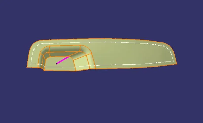
Step2:trim the class A with class C to get inside the portion.
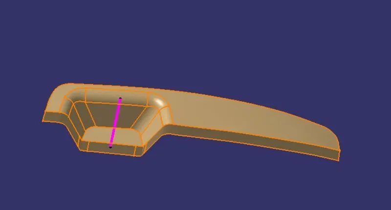
Step3:now,trim the B surface with the output of class A & C that will be parting surface with resspect to area.
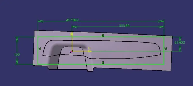
step4:extrude the sketch overall through the tooling direction are trim it with parting surface.
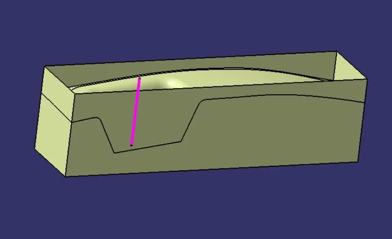
step5:final output of core design.
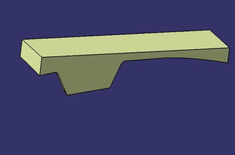
step6:closed part body of the core design.
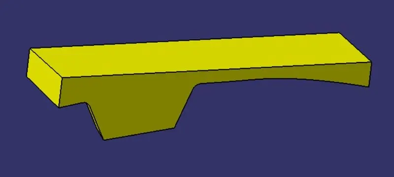
step7:now,take the intersection of the core design.
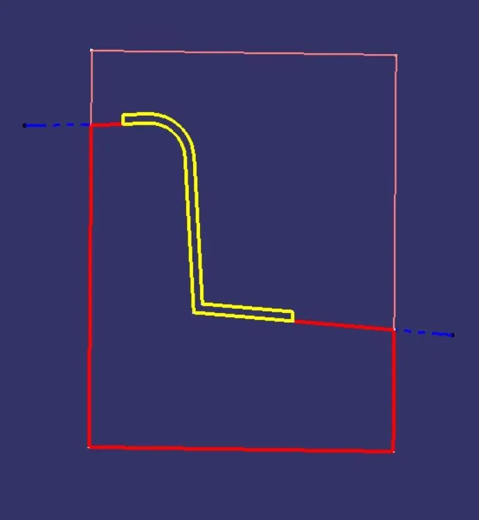
step8:similarlly,repeating the same as done for the cavity and trim it on other side surface.
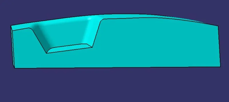
step9:Final close the surface of core & cavity design.
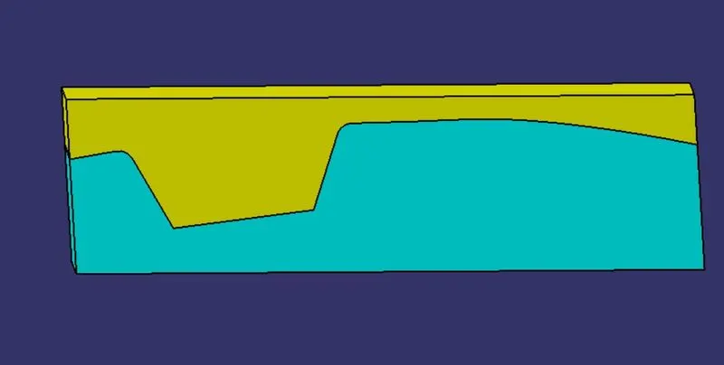
step 10: take the cut section view.
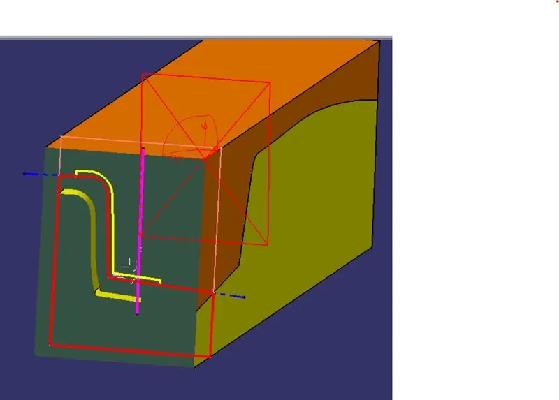
step11:parting line
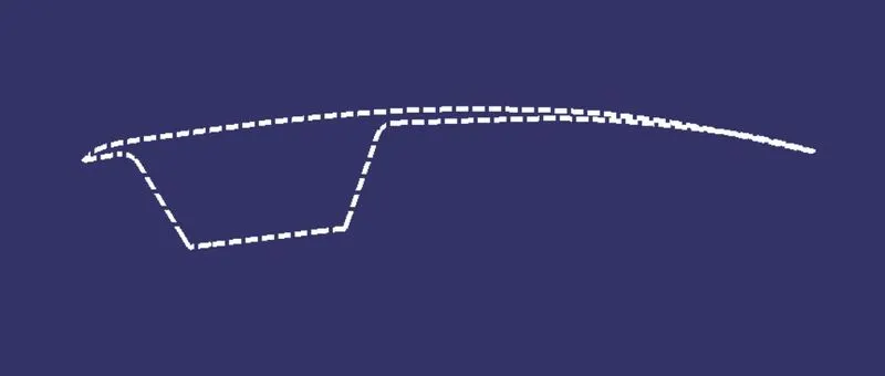
step12:parting line representation with component.
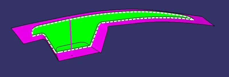
FINAL CORE AND CAVITY DESIGN:
CONCLUSION:
The design of core and cavity is done successfully.