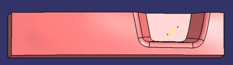
Week 8 - Challenge 5 - Core & Cavity Design
Core and Cavity Design:
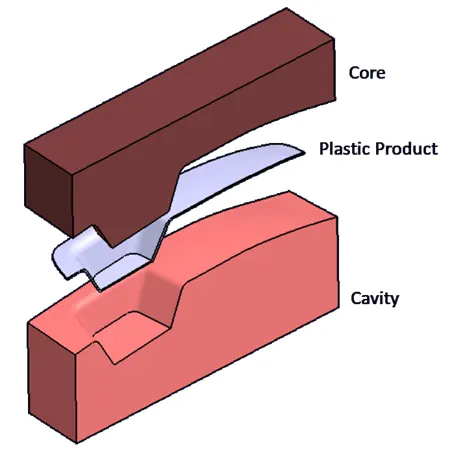
Aim and Objective:
- Creating Tooling Axis following OEM Standards.
- Preforming Draft Analysis on:
- Plastic Component / Solid Body (Switch Bezel)
- Core
- Cavity
Creating Tooling Axis:
- Injection moulding includes Core, Cavity, and Sliders to get a product its final Shape.
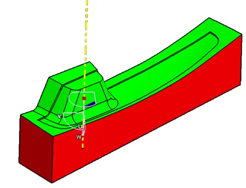
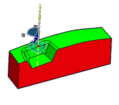
- Core, Cavity, and Slider move/side in a particular direction which is called Tooling Axis.
- Tooling Axis must be crated such that it will allow minimum friction between mould and solid body.
Bisection Method
- A surface can be taken as a reference to make a tooling Axis.
- In a Bisection Method, we take intersection at XY and XZ plane.
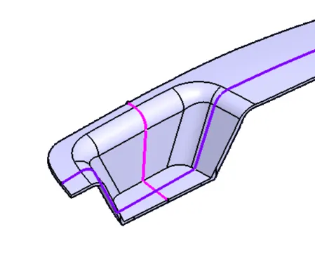
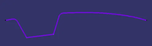
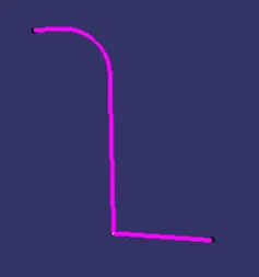
- Using these intersections we make lines that are almost parallel to Z axis.
- These lines are then Bisected together to form a Final Tooling Axis.
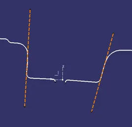
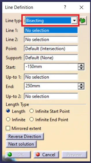
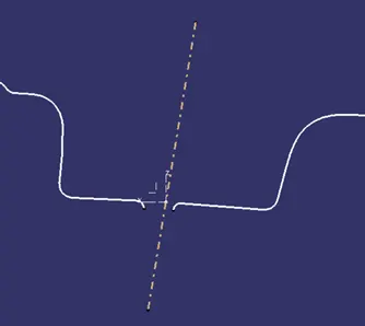
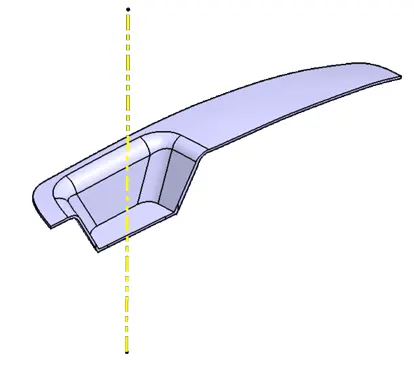
Note: Yellow line indicates Final Tooling Axis.
Draft Analysis:
Switch Bezel
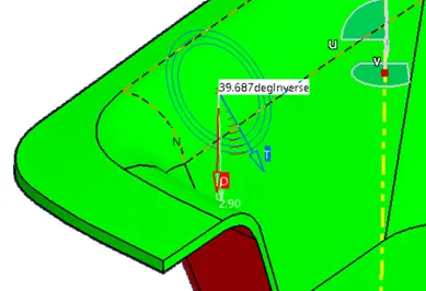
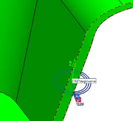
- The draft is an angle provided to the part with respect to the tooling axis to reduce friction between Part and Mould.
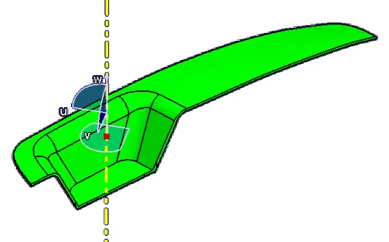
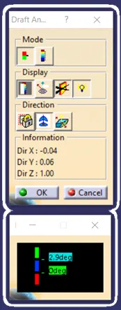
-
Part is provided with a minimum draft of 2.9 degrees.
Core:
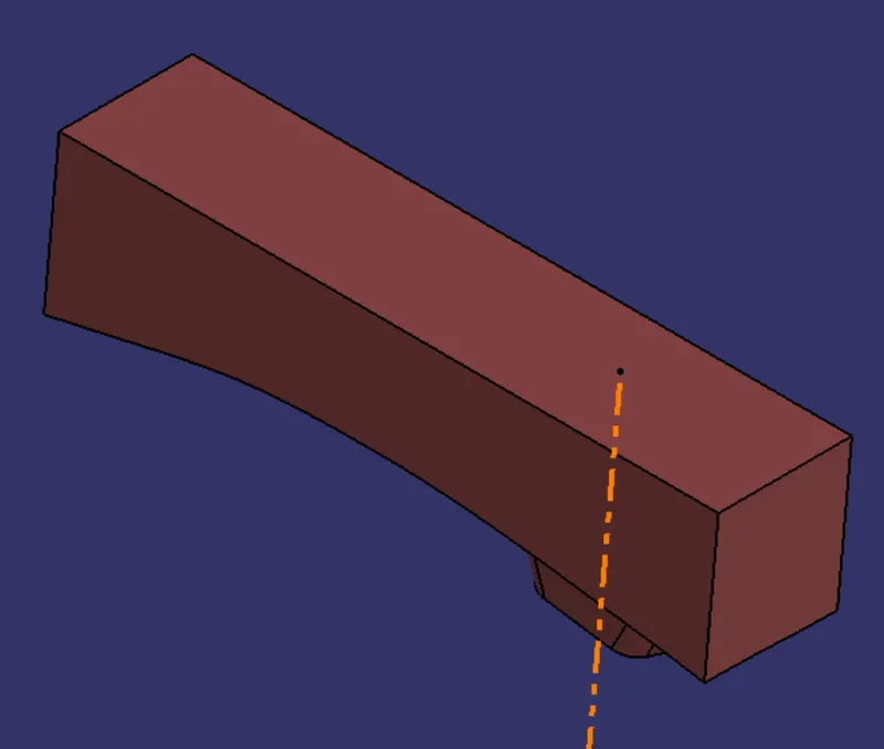
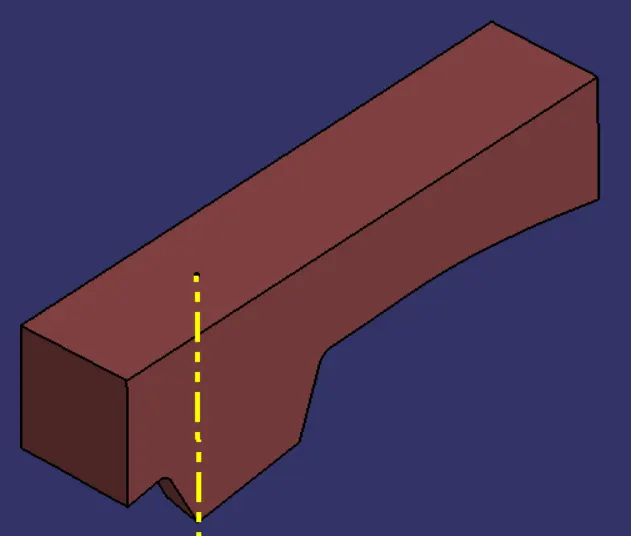
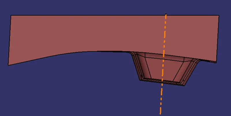
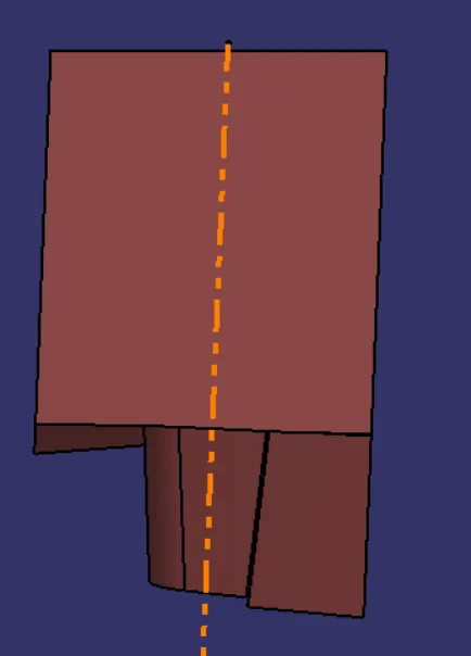
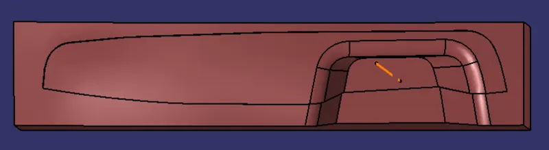
- Core is an extended portion of the mould from which molten plastic is injected inside the mould cavity.
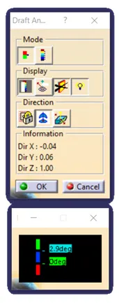
- Core is provided with minimum draft of 2.9 degrees.
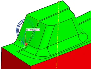
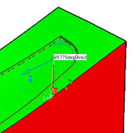
Screenshots of Core:
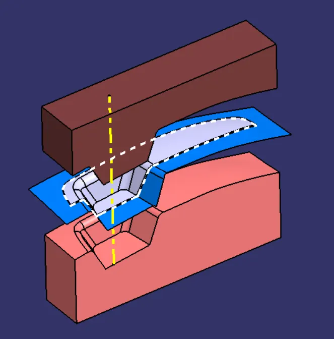
Core Isometric View
1. 
2. 
Core Front View
Core Side View
Core Top View
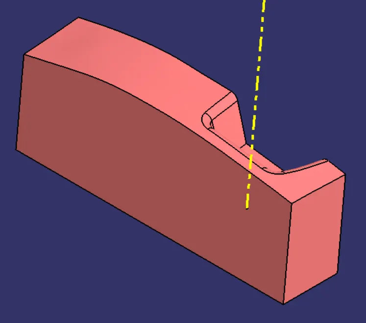
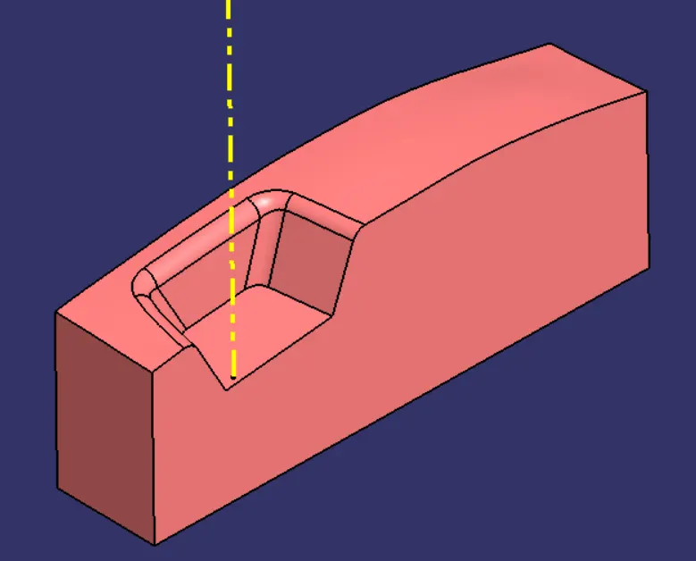
Cavity:
- Cavity is a depression portion of the mould which get filled with molten plastic to get the desired shape.
- Cavity is provided with a minimum draft of 2.9 degrees.
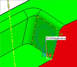
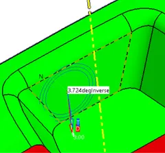
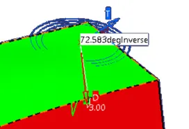
Screenshots of Cavity:
Cavity Isometric View
1. 
2. 
Cavity Side View
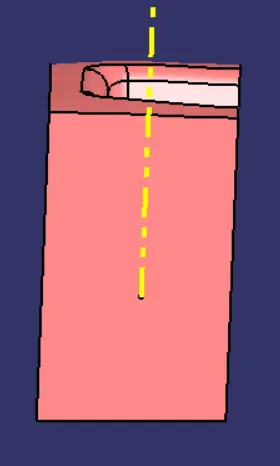
Cavity Front View
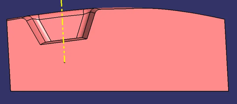
Cavity Top View