Coin Holder Design
Aim - Create the Coin Holder Plastic component through the given Class-A surface.
---------------------------------------------------------------------------------------------------------------------------------------------------
Class A Surface:
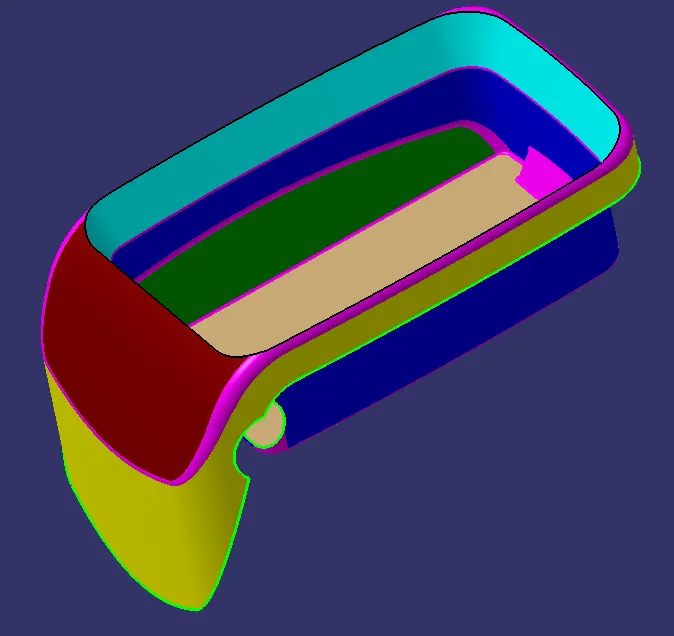
This is the given class A surface which is used to create the class B and C surfaces.
Tooling Axis:
The first step in creating the other surfaces is the construction of the Tooling Axis.
- Extract the base surface from Class A surface:
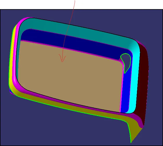
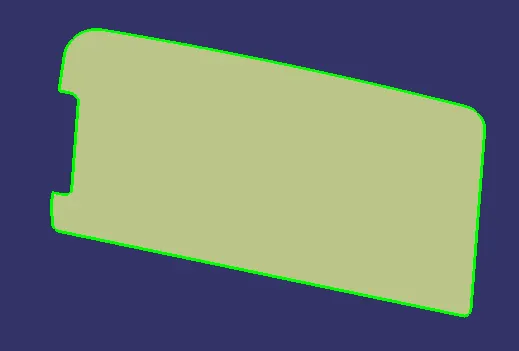
- Create a point on the extracted surface using the point command:
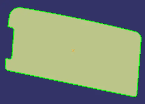
- Create a new axis system using the above point as the origin and create a line normal to the surface:
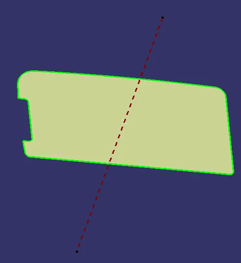
- This line is the tooling axis which is coloured brown for easy visualization:
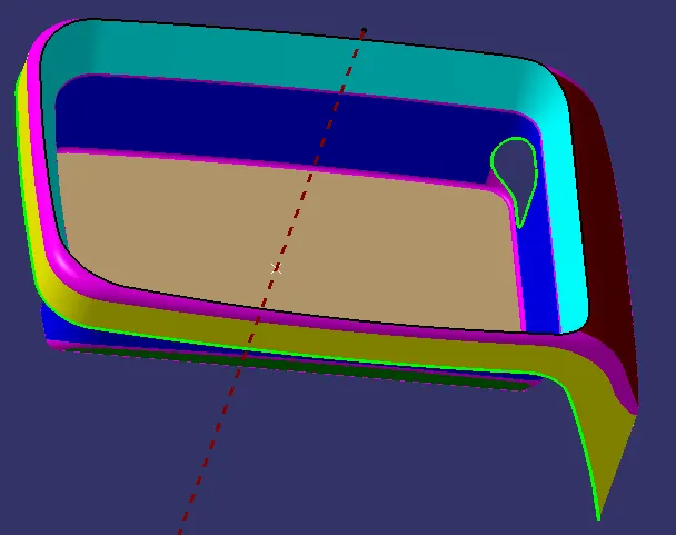
Publishing:
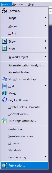
- Go to Tools and then Publishing:
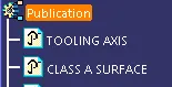
- Select the Class-A surface and the Tooling axis to publish.
Class B Surface:
Base:
- Class B Surface is created using the Class A surface.
- Firstly, extract the sides of the base from the Class A Surface:
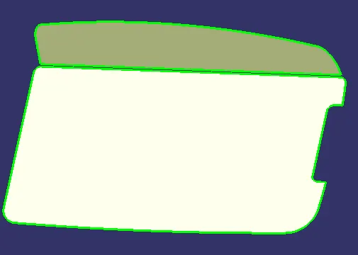
- Untrim the surfaces:
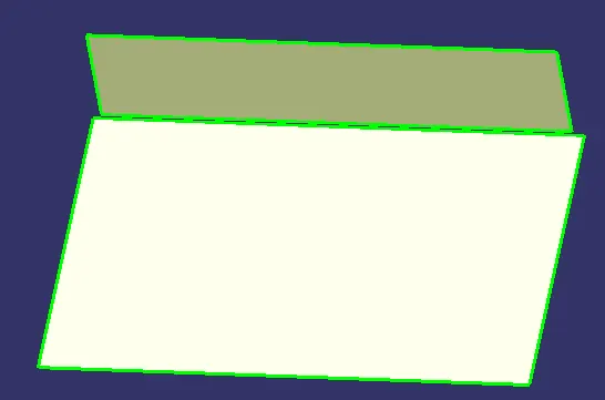
- Extrapolate the above surfaces using curvature continuity and point continuity:
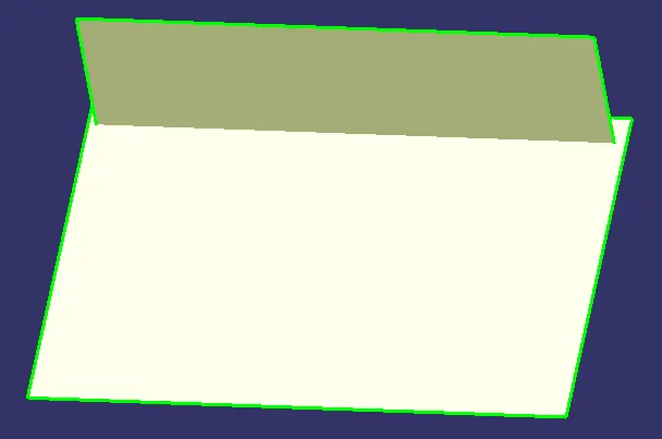
- Trim the surfaces together to get a single surface resembling the base in the Class A surface:
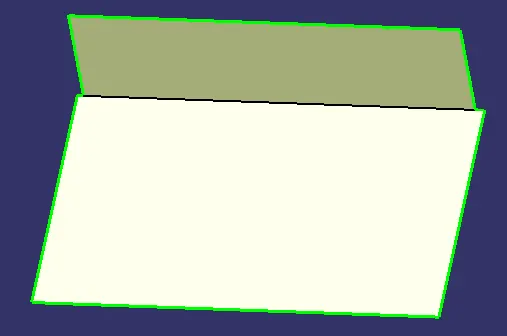
- The thickness of the component is 2.5mm so the above surface needs to be offset to a distance of 2.5 mm:
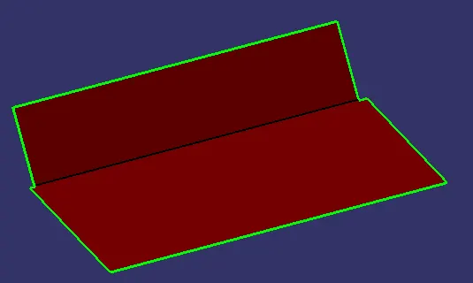
Side Walls:
- Extract the sidewall surfaces from the Class A Surface:
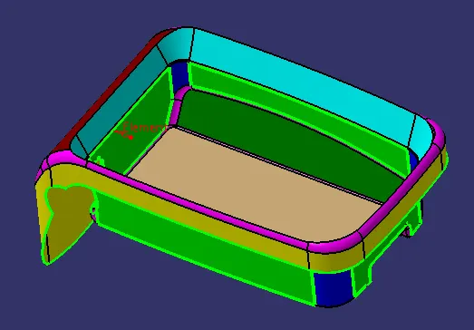
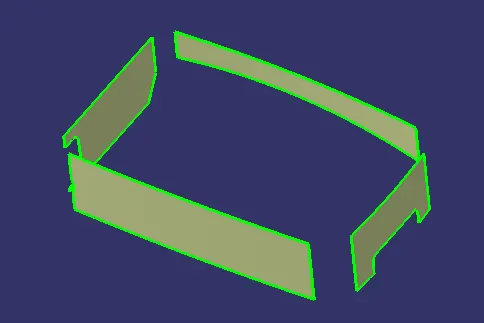
- Untrim the above surfaces and extrapolate them using curvature continuity and point continuity:
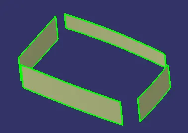
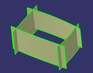
- Trim the surfaces to get a single surface that resembles 4 enclosing walls:
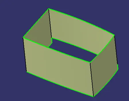
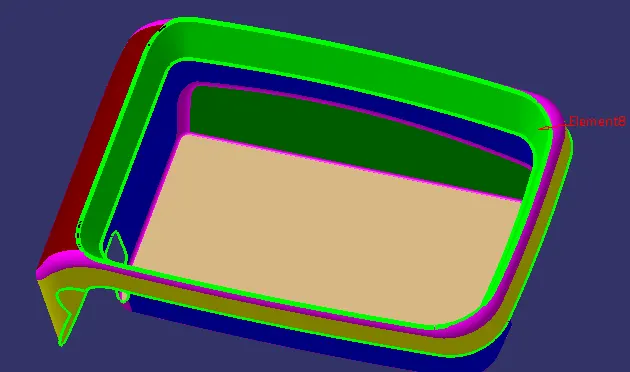
- This surface all needs to be offset for a distance of 2.5 mm outwards because of the thickness of the component. After trimming, provide fillets to the edges according to Class A Surface and the thickness:
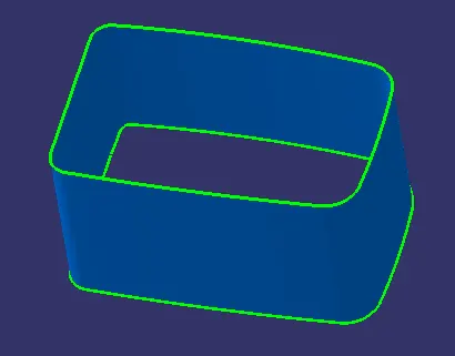
Upper Walls:
- Extract the upper wall surfaces from the Class A Surface using the Multi Extract feature including the fillets:
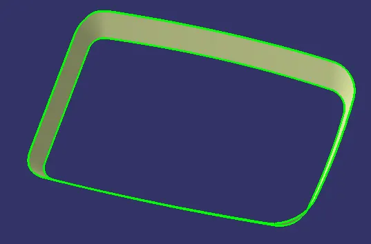
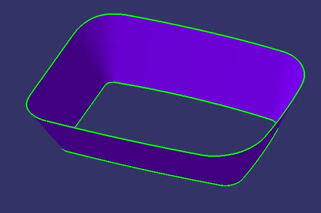
- Extrapolate the above surface using point and curvature continuity and create an offset of 2.5mm outwards:
Outer Flange:
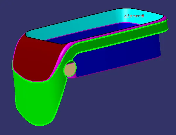
- The outer flange surface needs to be created in two steps.
- Firstly, extract the enclosing surface from the Class A Surface:
 |
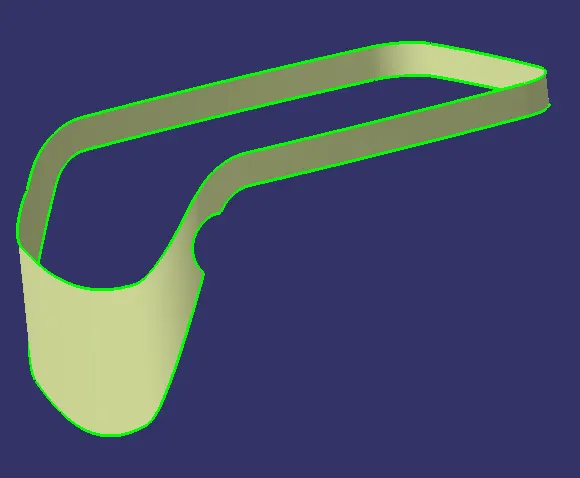 |
- Extrapolate the above-extracted surface using the curvature sand point continuity:
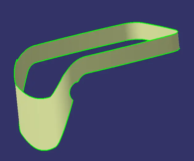
- Now, extract the remaining surfaces of the outer flange from the Class A Surface:
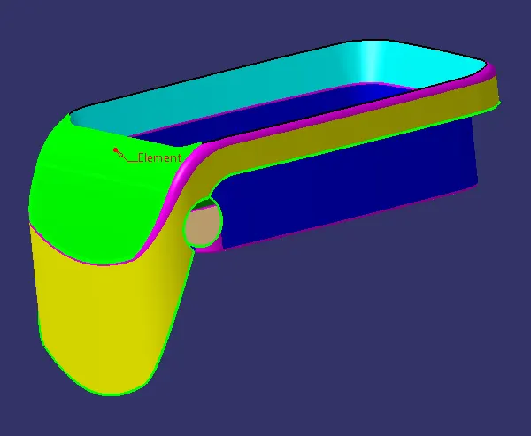

- Untrim the above-extracted surfaces and join them using the 'Join' feature and then extrapolate the resulting surface.
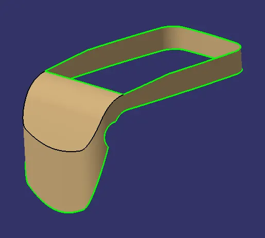
- Create offsets of the above surfaces. The offset needs to be created inwards because the outer flange surface in Class B Surface will be below the outer flange surface in Class A Surface:
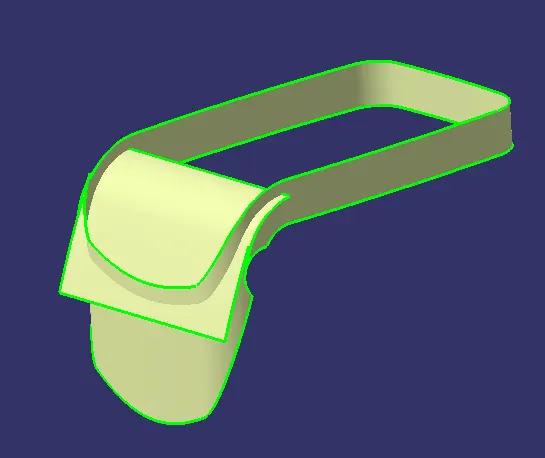
- Finally, trim the surfaces together and provide a different colour to the resulting surface:
Pad:
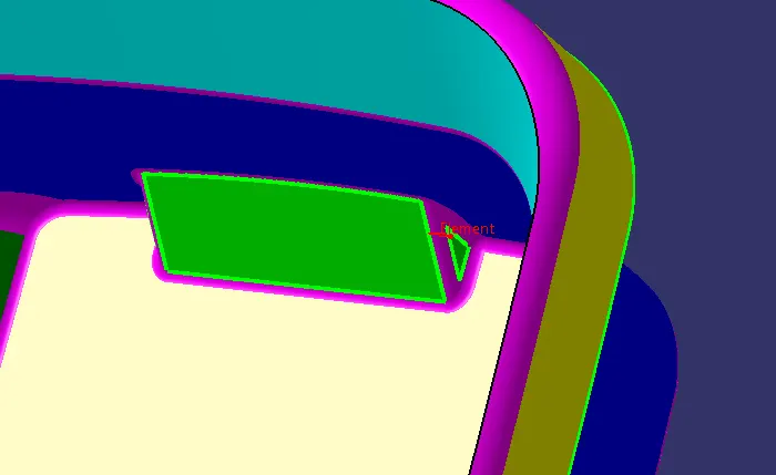
- In Class A Surface, there is a small pad. For Class B, the walls of the pad need to be extracted from the Class A Surface:
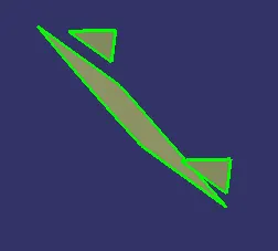
- Untrim the above surfaces and extrapolate them using the curvature continuity and point continuity:
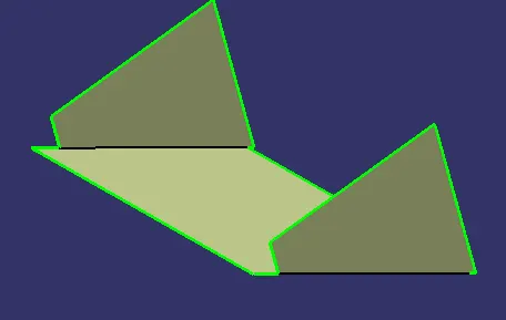
- Create an offset of the above surface and provide it with a different colour:
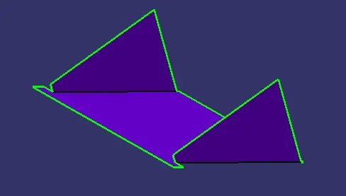
Initial Trims:
- Trim the base and the sidewall surfaces first, using the Trim feature:
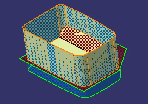
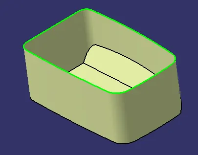
- Trim the above surface and the top wall surface together using the Trim feature:
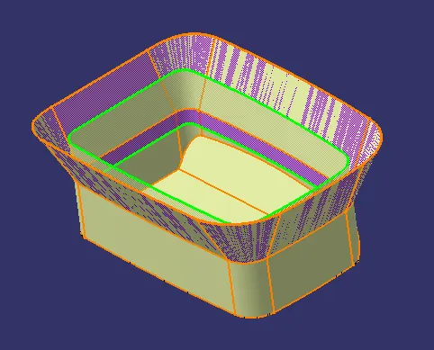
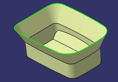
- Now, trim the above surface and the outer flange surface together using the Trim feature:
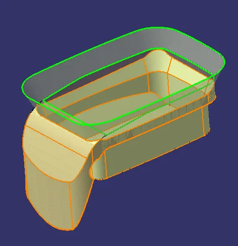
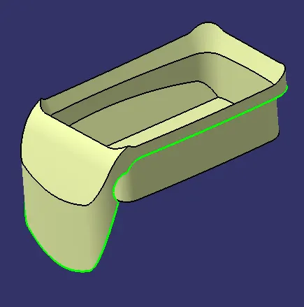
- Extract the small flat surface at the top from the Class A Surface:


- Untrim the extracted surface and extrapolate it from all four boundaries.
- Offset the extrapolated surface to 2.5 mm and trim it with the last trimmed surface:
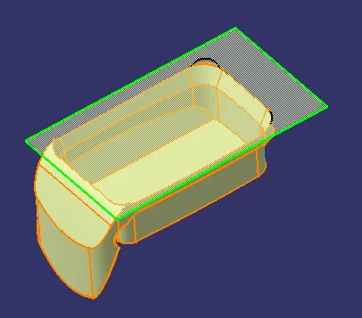
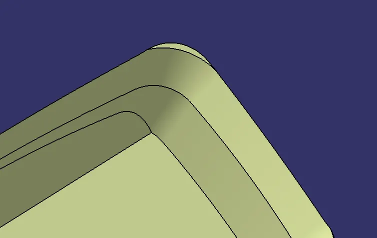
- Finally, trim the above surface and the pad surface using the Trim feature:
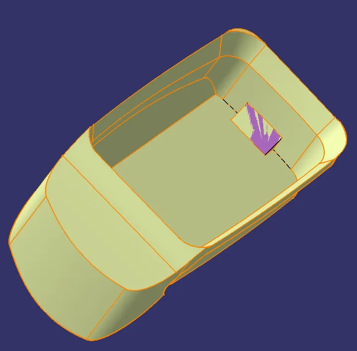
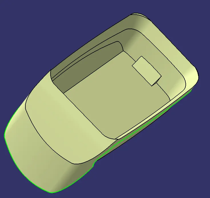
Fillets:
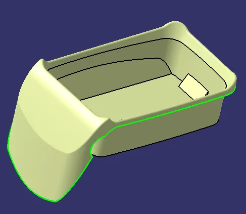
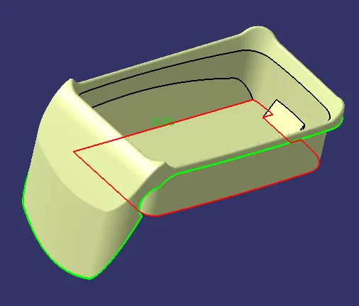
- Now, the fillets are applied to all the edges using the measurement from the Class A Surface and the thickness of 2.5 mm.
- Firstly, provide the fillet at the top edge:
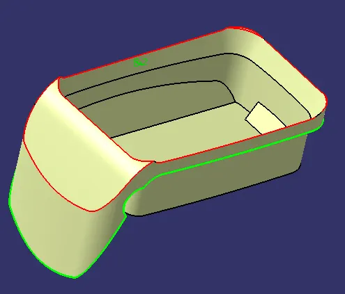
- Provide the fillet at the base edges:
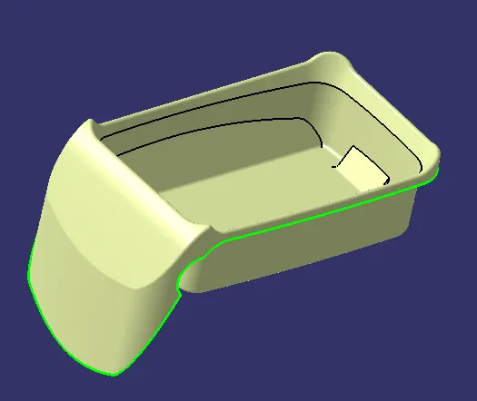
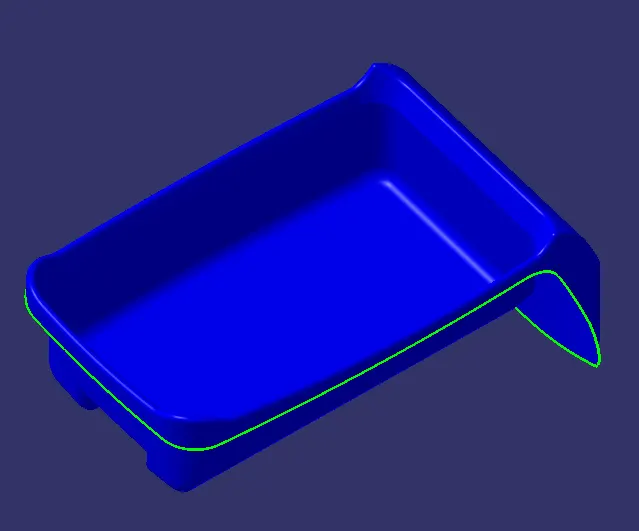
- Similarly, provide the fillets to the sidewall edges. The final surface after filleting is the Class B Surface:
Class C Surface:
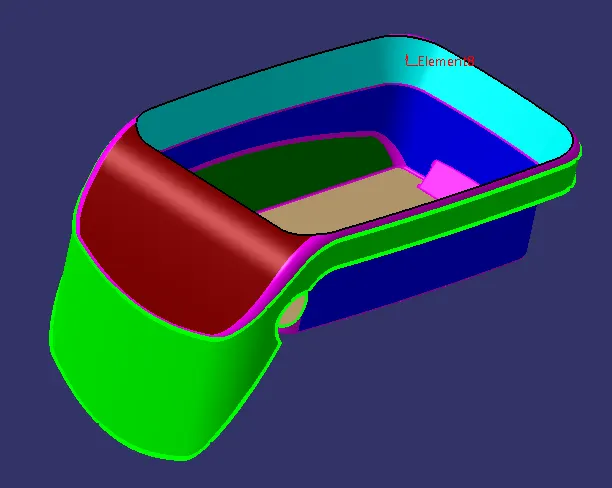
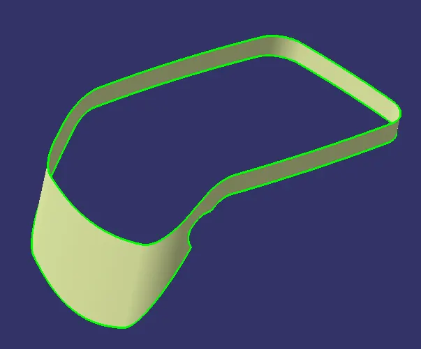
- EXtract the enclosing walls of the outer flange using the Multiple extract feature:
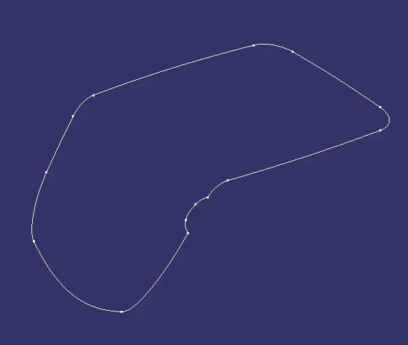
- Extract the boundary of the Class A Surface:
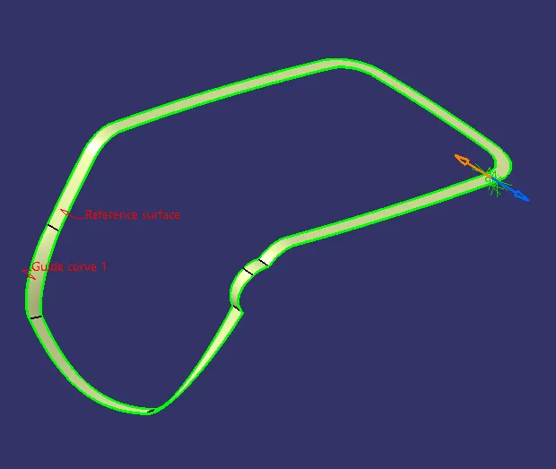
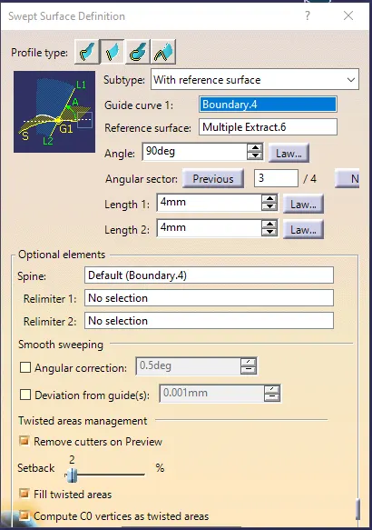
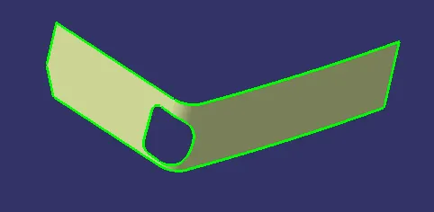
- Use the Sweep feature, with Subtype as 'With reference Surface'. Choose the guide curve 1 as the above-extracted boundary and the reference surface as the above-extracted surface from the Class A Surface. choose the angle as 90 degrees:
- Now, the Class C Surface for the section needs to be created.
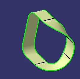
- Extracted the boundary of the section and the nearby surfaces:

- Again use the same Sweep command with the same subtype and angle. Choose the guide curve ass the extracted boundary and the reference surface as the above-extracted surface:
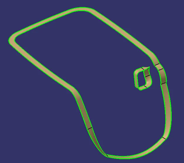
- Following are the Class C Surfaces:
Final Trims:
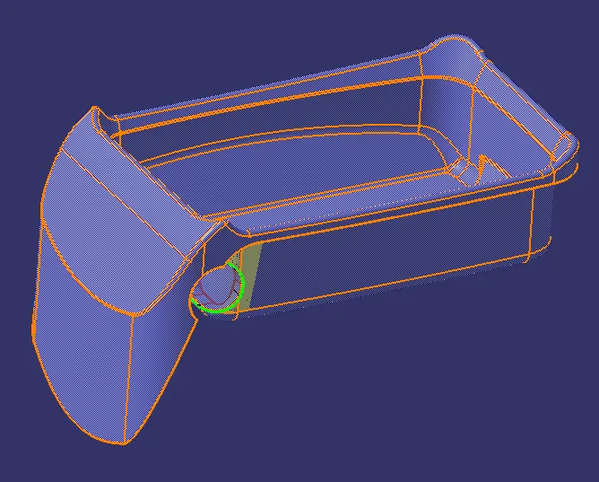
- Firstly, trim the Class B Surface and the Class C Surface of the section:
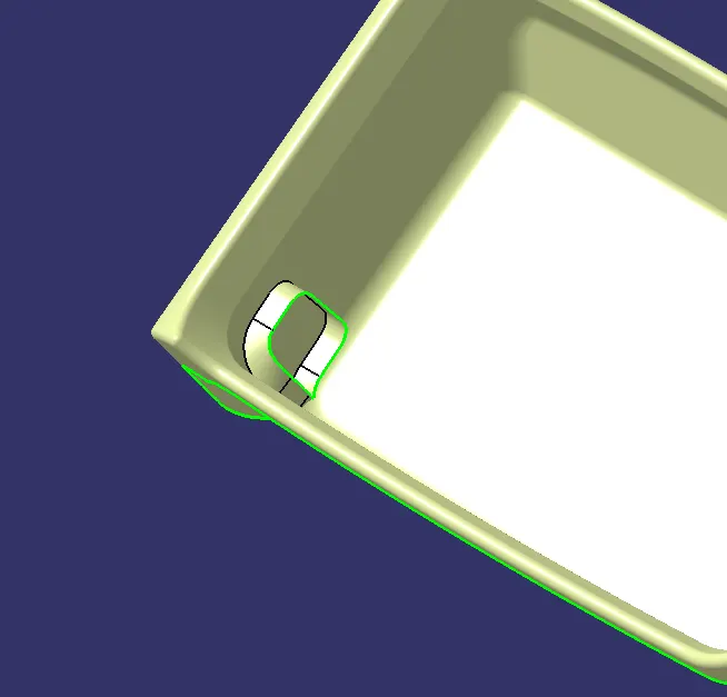
- Now, trim the above surface and the other Class C Surface:
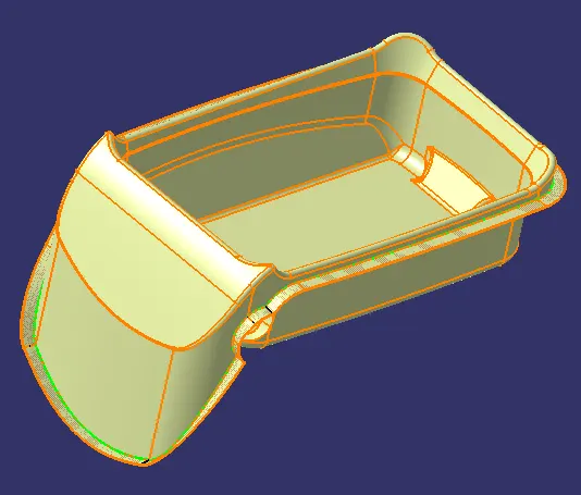
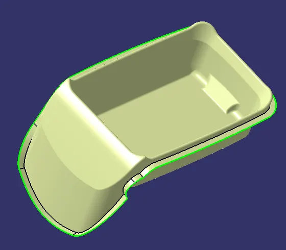
- Finally, trim the above surface and the Class A Surface to get the final enclosed surface:
Part Body:
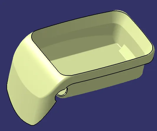
- Use the 'Close Surface'
 feature, the final closed surface is converted into a solid body:
Draft Analysis:
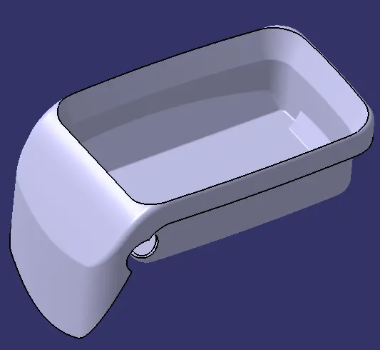
- For the draft analysis, we need the solid body and the tooling axis.
- Firstly customize the view parameter to change the mesh shading to the material.
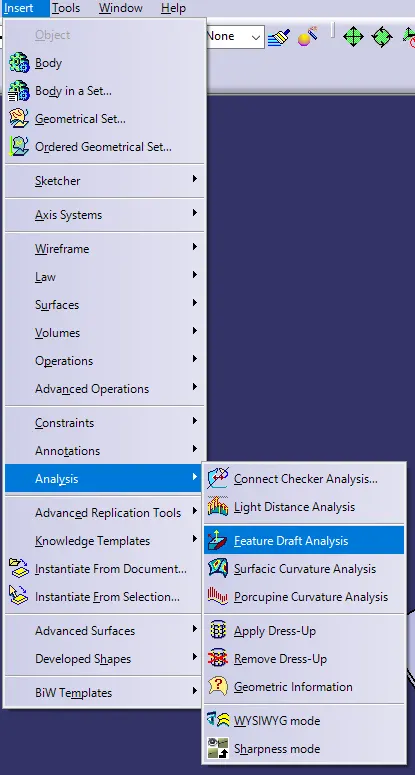
- Go to Tools →">→→ Analysis →">→→ Feature draft Analysis
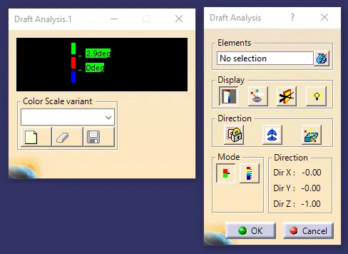
- Choose the Compass from the above dialogue box and drag-and-drop it on the Tooling Axis.
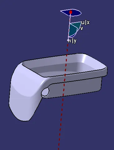
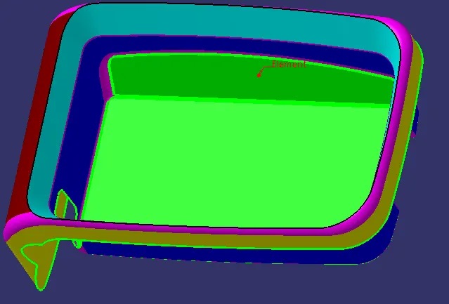
- Choose the solid body as the Element:
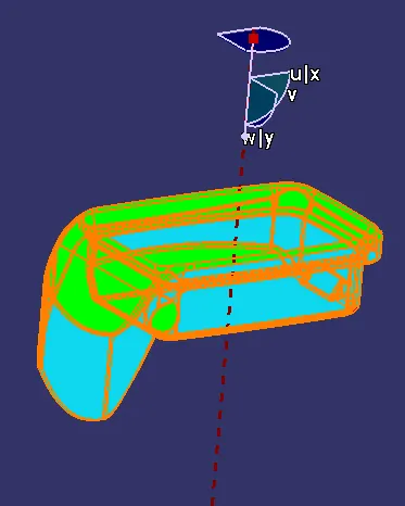
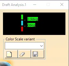
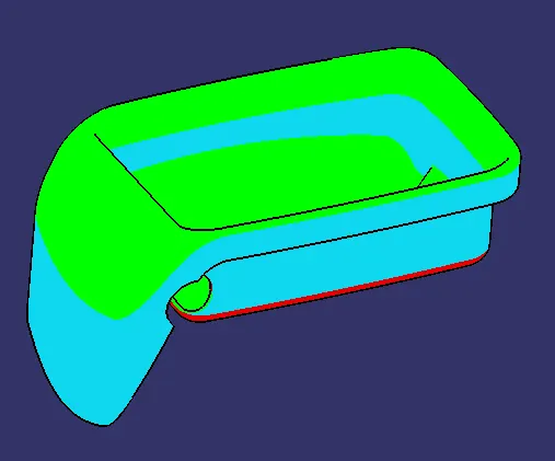
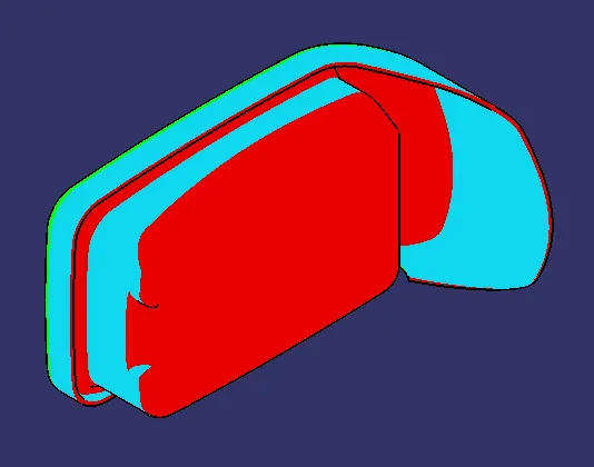
- The green region has a minimum draft of 3 degrees and the blue region has a negative draft (this is because of the reverse direction). There is no cyan region on the body which indicates that there is no region with a 0-degree o draft.
Remarks:
- There are a lot of surfaces in the cyan colour that indicates zero draft angle. Thus, these surfaces should be provided with some draft angle in order to reduce defects during manufacturing.
Conclusion:
- The Class B and Class C surfaces are successfully created from the given Class-A surface.
- The Class A, Class b and Class c surfaces are trimmed together to create the final close surface of the component.
- The solid body is successfully created using the closed surface.
- the draft analysis is successfully completed.