Week 8 - Challenge 4 - Coin Holder Design
COIN HOLDER
AIM: To create coin holder part model by the given class A surface and also creating tooling axis by bisection method and creating class B and class C surface.
OBJECTIVES:
- To ensure proper tree structure is followed.
- Geometrical sets should have a proper name based on the sketches present inside of it.
- All the sketches should be created under the geometrical set.
- Use of the close surface features to make a solid body from the surface.
- To publish the tooling axis, class A,B & C surfaces.
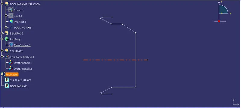
PART 1: Creation of tooling axis
Tooling axis is created to determine the direction of mold opening and closing. Draft around the different faces is provided along tooling axis. Here the tooling axis is created in the Y direction with reference of a middle intersect of the component.
PART 2: Creating class B surface
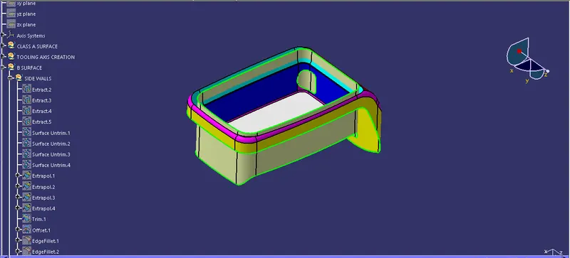
- It is created from class A surface.
- Surfaces from class A are extracted.
- The same surfaces are untrimmed.
- These surfaces are extrapolated.
- The extrapolated surface is offset by the given values.
- Creating SIDE WALLS from class A surface
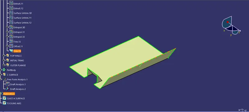
2. Creating Base.
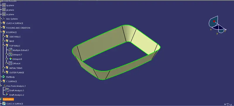
3. Creating Top wall.
4. Creating outer flange.
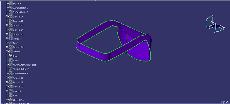
5. Trimming all the surfacesand getting a class B surface.
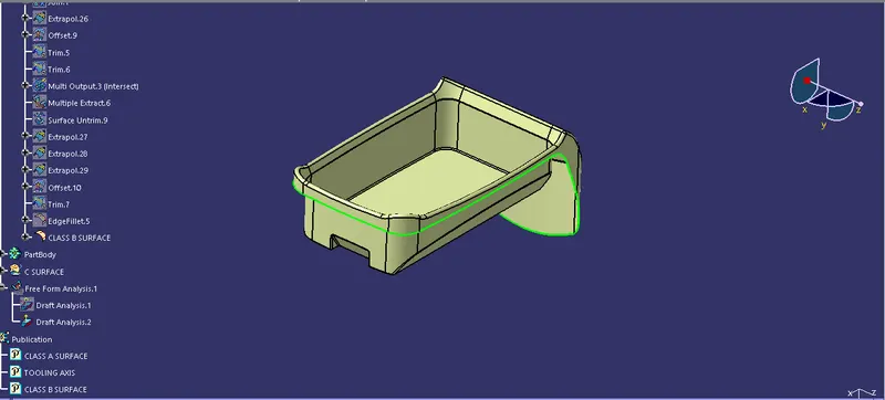
PART 3: Creating class C surface
- Creating boundaries from class A surface.
- Performing sweep operations at 90 degrees with respect to the extracted boundary and surfaces.
- The sweep command to be used is “line” profile type with “with reference surface” option.
- Connecting the swept part with the help of trim. The final trim is class C surface.
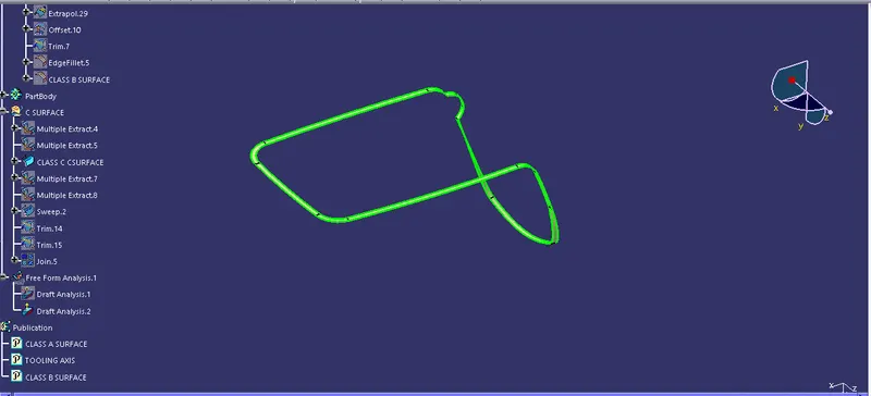
Creating a final surface with the help of trim and fillets operation:
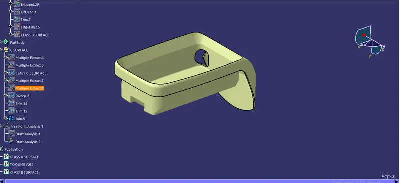
PART 4: Creating the final component.
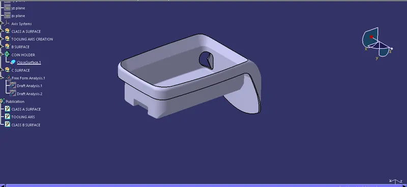
PART 5: Draft analysis
Draft analysis: Draft is an angle provided on the faces of a component with respect to the tooling axis. Providing draft ensures easy removal of component from the mold cavity. Draft analysis helps us determine draft of every faces/surface of a component with respect to the tooling axis.
Draft analysis is as follow:
- We have to check continuity of the surface.
- We find tooling direction with the help of tooling axis.
- By using draft analysis tool we put compass on the tooling axis, and get the results of draft analysis.
- Draft analysis of class A surface
- Isometric view
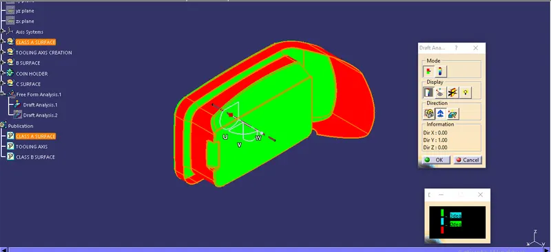
- Front view
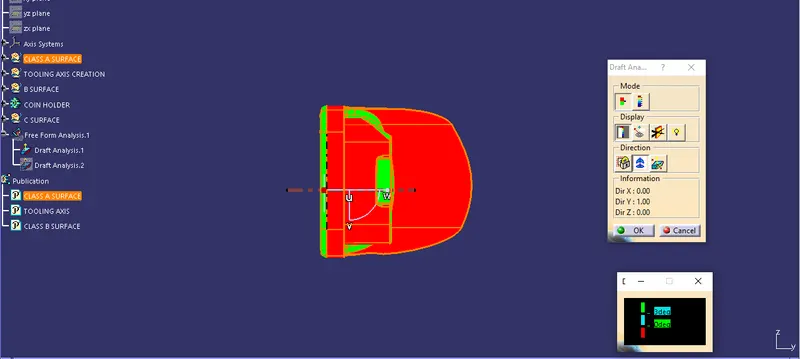
- Top view
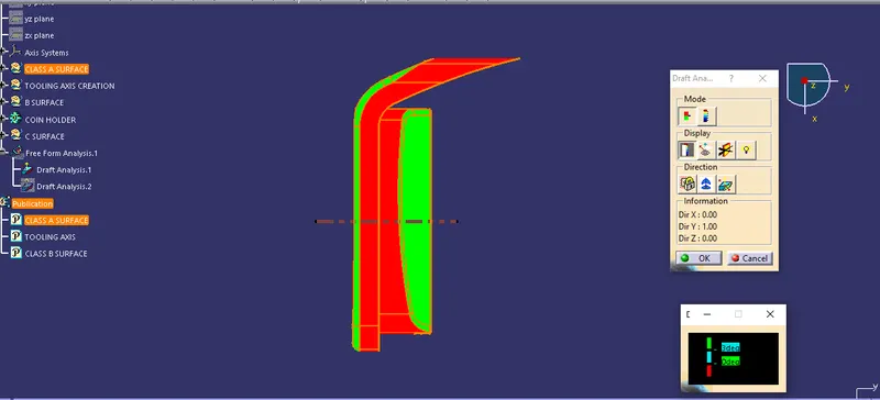
- Side view
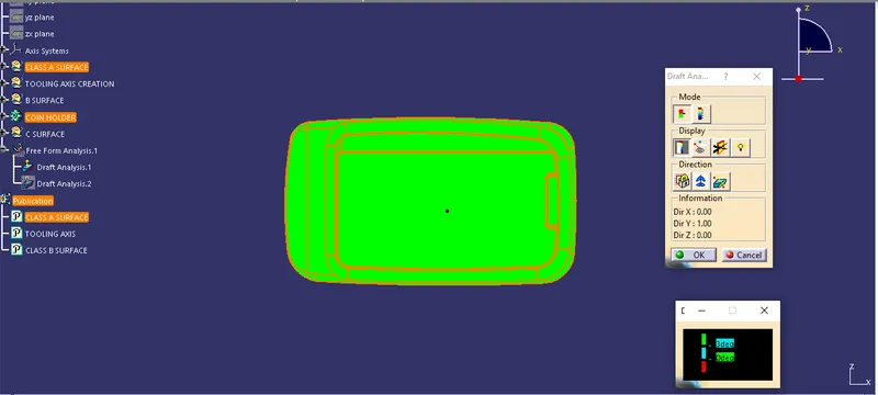
Draft Analysis Report:
From this analysis we can observe that there are many surfaces that require draft provided. The surface in red color represents angle lesser than 0 degrees. In this component the faces are parallel to tooling axis. There should be minimum of 3 degree draft provided on those faces.
- Draft analysis of the final component
- Isometric View.
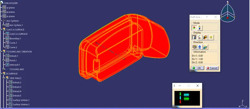
- Front view.
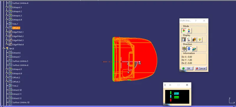
- Top View.
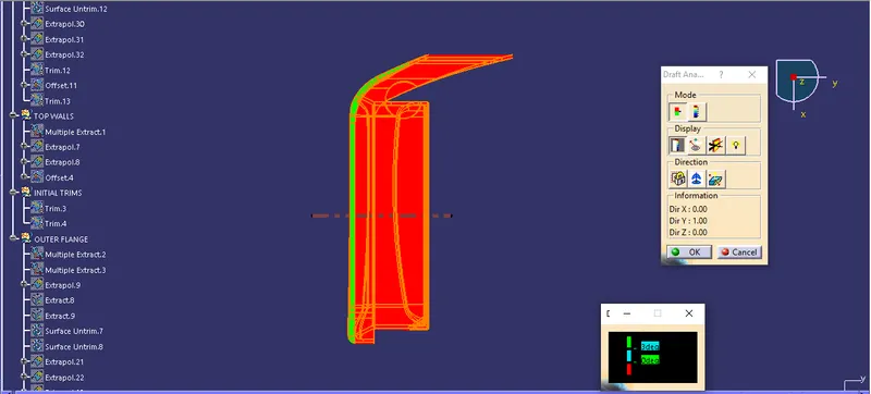
- Side view.
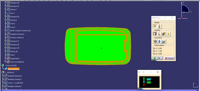
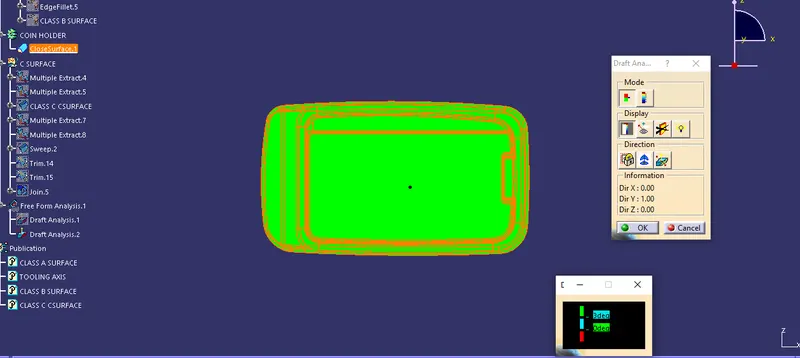
Draft Analysis Report:
From above images it can be inferred that the red surfaces need draft angle to be provided over them.