Week 8 - Challenge 4 - Coin Holder Design
Aim/Objective:
Create the Coin Holder Plastic component through the given Class-A surface. To begin with, the tooling axis for the given Class-A Surface should be created meeting the requirements of the draft angle and at the end perform the Draft analysis on the model.
Take the Thickness of the component to be 2.5 mm.
Report:
Terms used:
- Class A surface: It is outermost surface of automobile which gives aesthetic look to vehicle. It is physically touchable. It is obtained from clay modeling by reverse engineering. This surface is given input to plastic product designer to work.
- Class B surface: This surface is created by taking offset from class A surface. It is surface on which all engineering feature like screw bosses, dog house, ribs & mounting are created.
- Class ‘C’ surface: This is surface which joins class A & class B together.
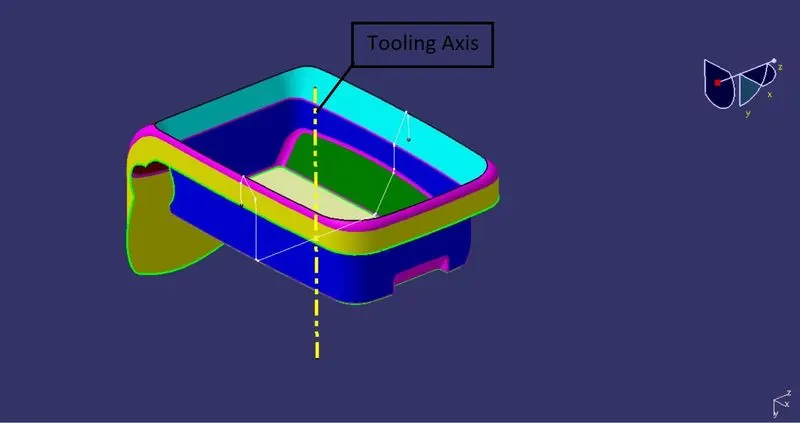
- Tooling axis: It is the direction in which core & cavity opens & closes.
Method followed:
- Checking continuity of class A surface.
- Deciding feasible tooling direction & creating tooling axis.
- Performing draft analysis on class A surface.
- Creating class B surface from given class A surface.
- Creating class C surface to join A & B class surface.
- Creating solid feature by using closed surface.
- Performing draft analysis on final plastic component.
- checking continuity of given class A surface:
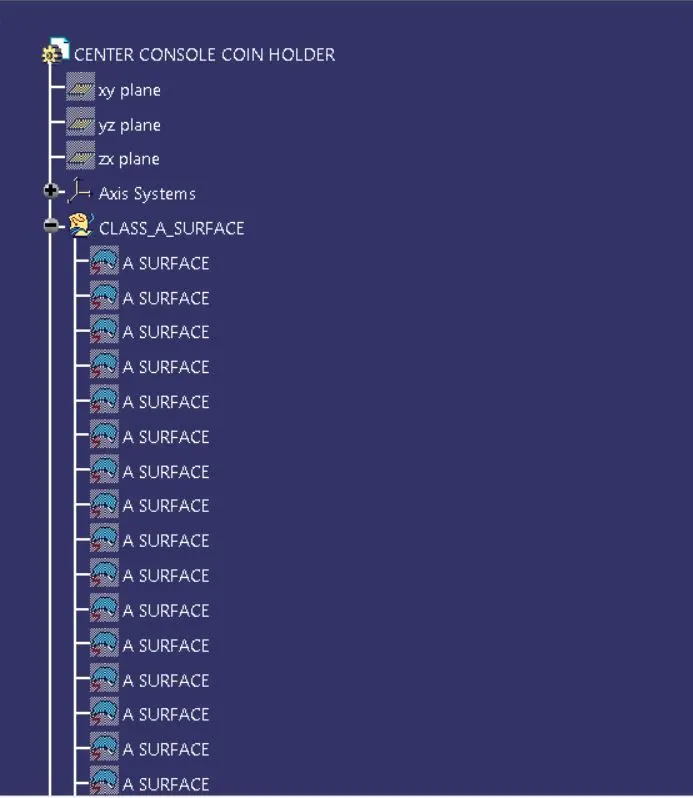
- First given file is in IGES format. So we have to join this all small surface patches to create class A surface.
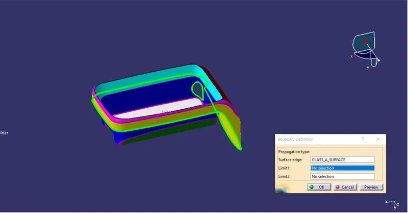
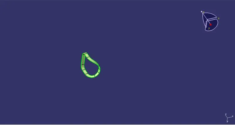
- We have to check continuity of given class A surface to ensure class A surface is properly joined or no discontinuity present. This can be done by using join or boundary command in CATIA. By looking visually in below image we see that surface has continuous connected boundary as highlighted by green line. Also this boundary separated into two domains.
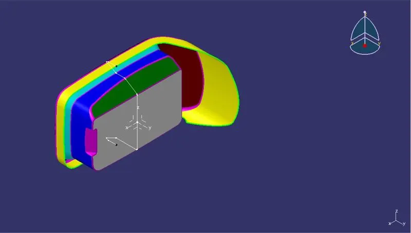
- Extracting the boundary of given class A surface we also check that continuity visually. Below figure shows coin holder model has continuity in class A surface.

- Creating tooling axis direction:
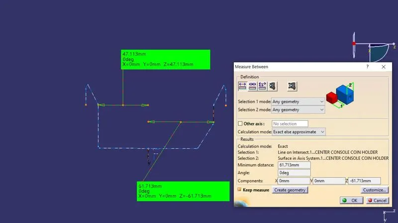
- Next step is to decide tooling axis direction. Analyzing the model to see which faces will create problem for tooling. Taking intersection of class A surface with YZ plane of axis system. Side faces hasn’t provided draft these faces will create problem during tooling. Class A surface should need to modify with draft on side faces. This can be done by class A designer. But now we proceed with same.
-
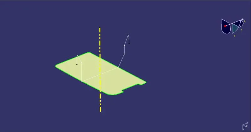
In this case, tooling axis is normal to base surface. Consider Y axis as tooling direction. Extract the base surface. Create point on surface & creating line normal to base surface passing through that point. This is our tooling axis.
- Performing draft analysis on class A surface:
- To perform draft analysis. Go to insert < Analysis< Feature draft analysis.
- Switch customize view parameter mode to
- Click on compass icon & align it with the tooling axis & click on the surface, we will get our results.
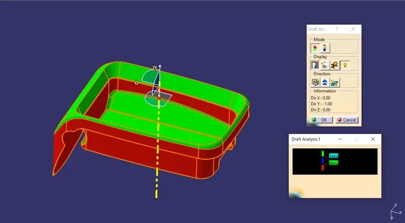
- From the below image it is seen that surface in green color has more than 3° draft which is most required for tooling feasibility. Also see color variant display box.
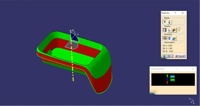
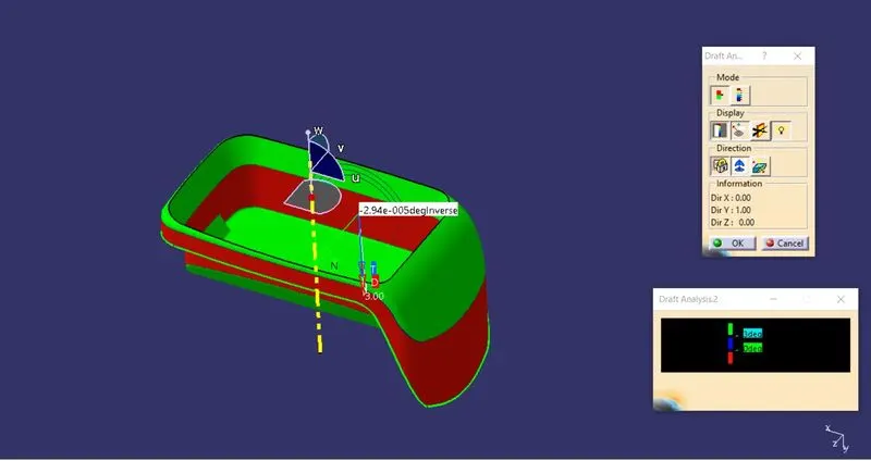
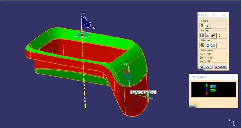
- Below image shows running point draft analysis.
- Creating class B surface from given class A surface.
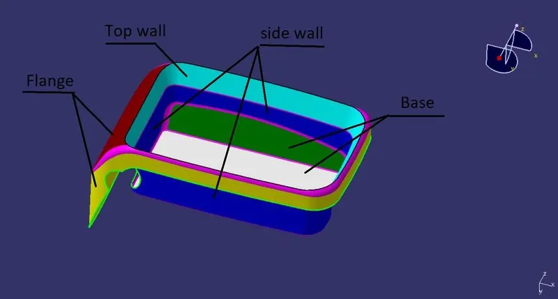
Divide class A surface into surfaces namely side wall, base, top wall & outer flange as shown below image. Work on each surface separately to obtain class B surface.
- Side wall: surface marked in blue color.
- Base: surface marked in white & green color.
- Top wall: surface marked in cyan color.
- Outer flange: surface marked in yellow & chocolate color.
Follow the same procedure for all surfaces.
- Extract the class A surface.
- Un-trim the surface.
- Extrapolate untrimmed surface.
- Trim unwanted extra surface.
- Offset it by 2.5 mm distance.
- Applying fillet as per formula to obtain uniform wall thickness.
*If surface need to offset outside then fillet = class A surface fillet + thickness of part.
*If surface need to offset inside then fillet = class A surface fillet - thickness of part.
Side wall:
- Extracting the class A surface.
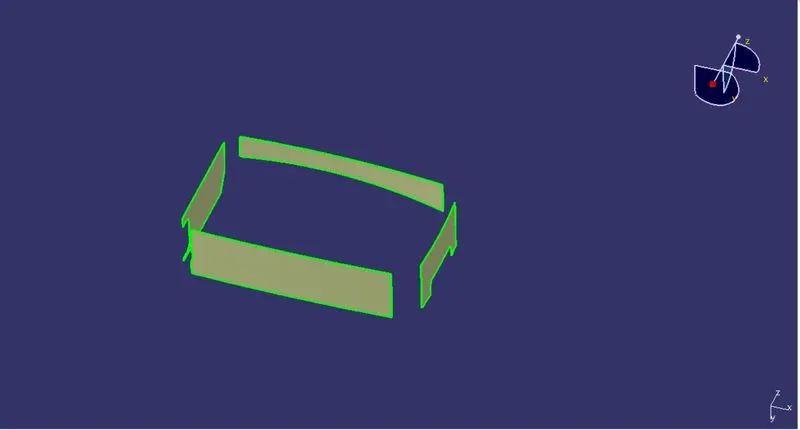
- Un-trim the extracted surface.
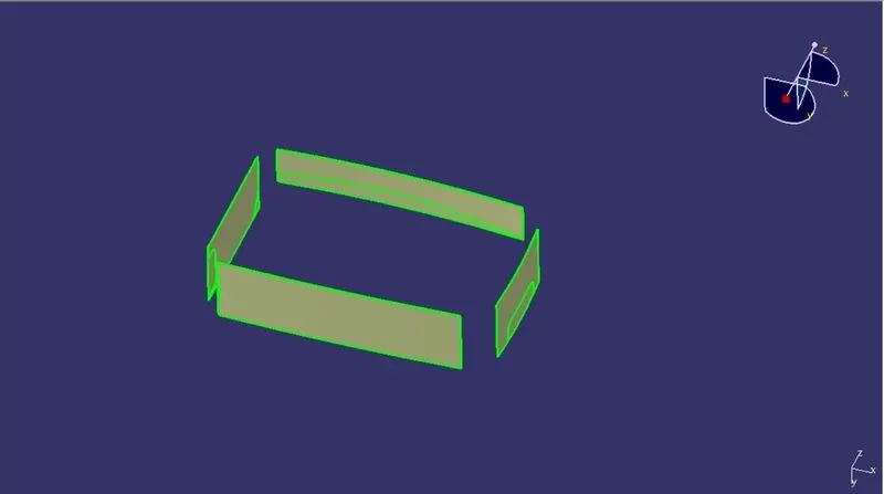
- Extrapolate the untrimmed surface.
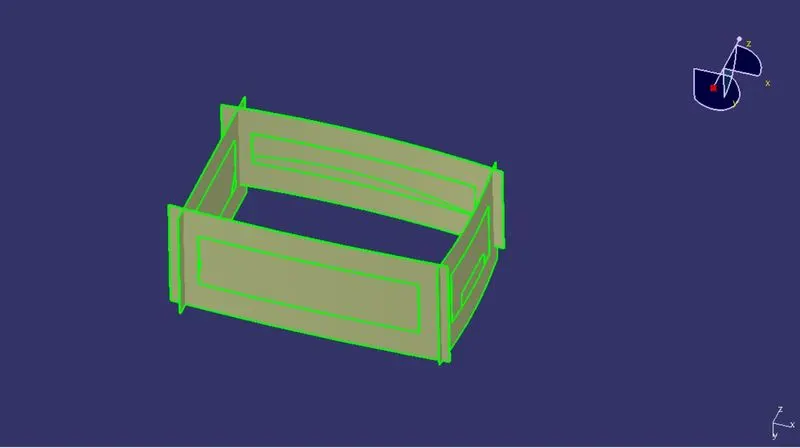
- Trim unwanted extra surface.
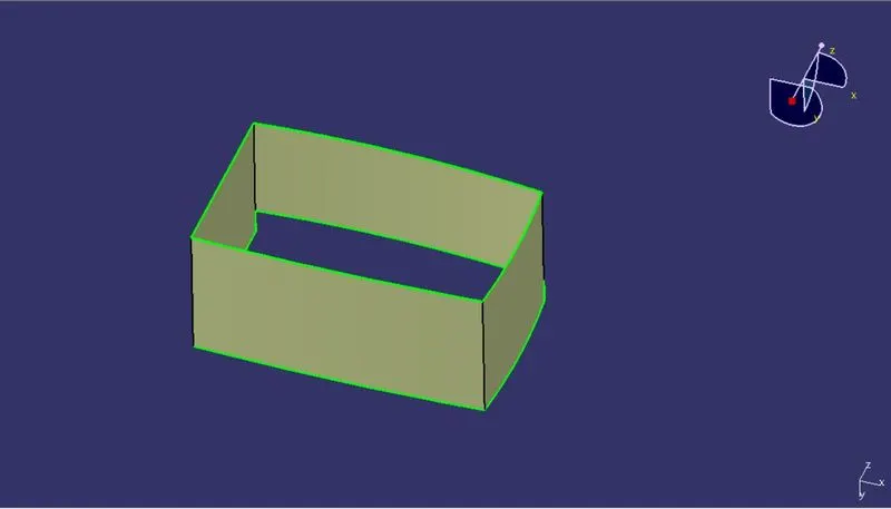
- Offset it by 2.5 mm distance.
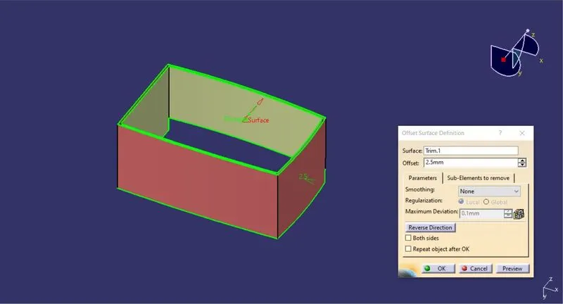
- Applying fillet as per formula
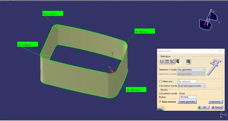
-
Following same procedure for rest of all surfaces & we get following surfaces.
- Base:
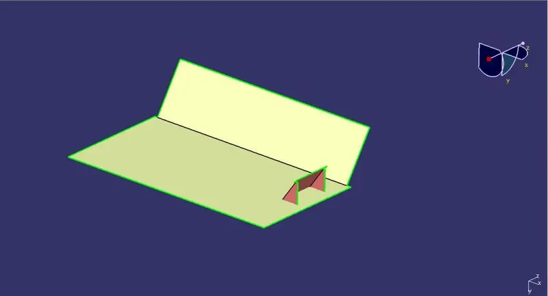
- Top wall:
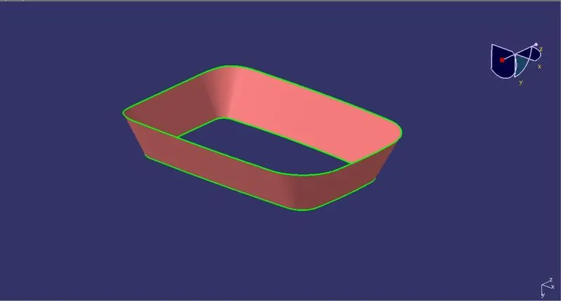
- Outer flange:
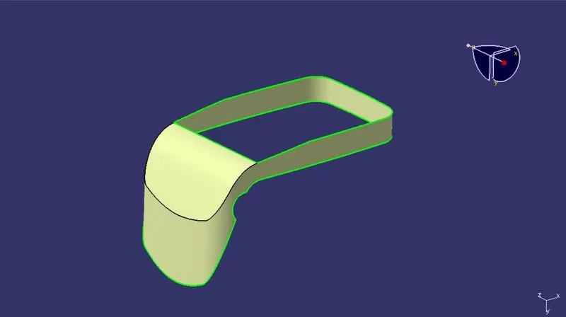
- Trim all these surfaces together to get final class B surface. Fillet edges of class B surface as per formula. Apply fillets value 1 mm to remaining edges to avoid sharp corner.
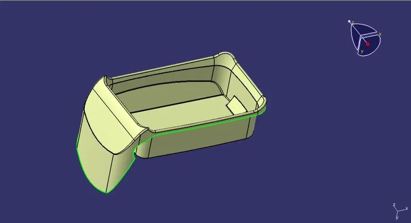
- Creating class C surface to join A & B class surface.
Follow the below procedure to obtain class C surface.
- Extract the outer boundary of class A surface & surface surrounding outer boundary.
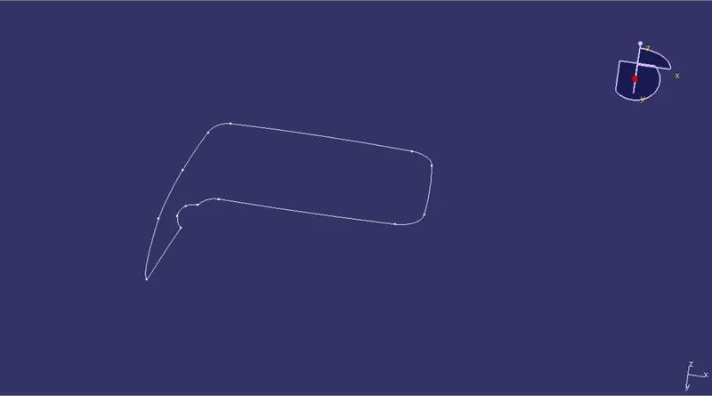
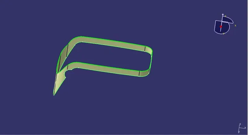
- Swept class A surface along boundary at 90° angle with length 10 to 15 mm.
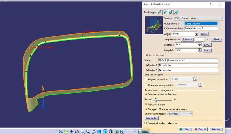
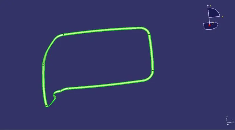
- Trim this swept surface with class B surface.
- Join this trimmed surface with class A surface.
- To create inside cutout follows the same procedure as for swept surface of outside boundary.
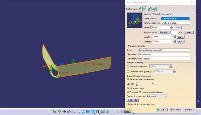
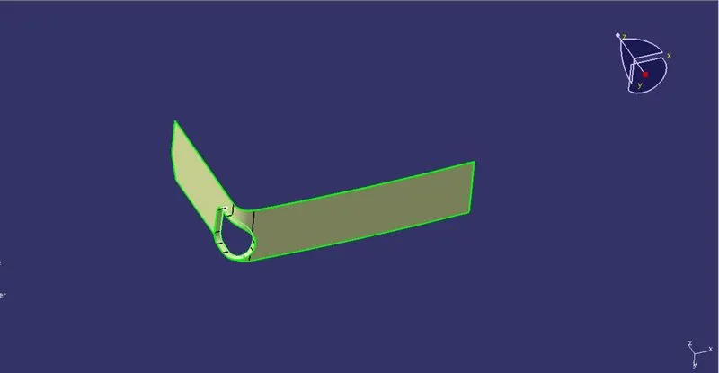
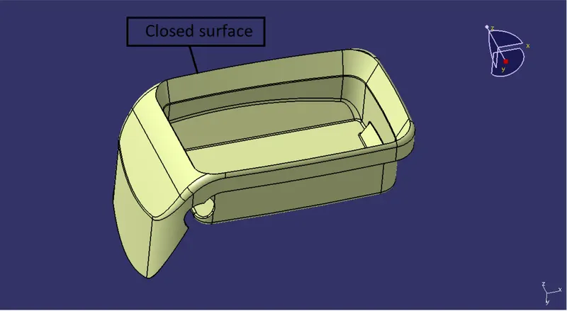
- Trim this surface with earlier joined surface. So this is our closed surface.
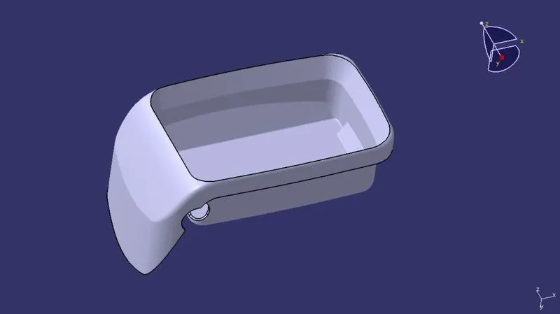
- Creating solid feature by using closed surface.
- Solid model is created from closed surface in the part workbench by using close surface command.
- Performing draft analysis on final plastic component.
- Performing the draft analysis again with the same procedure as mentioned above for the class A surface.
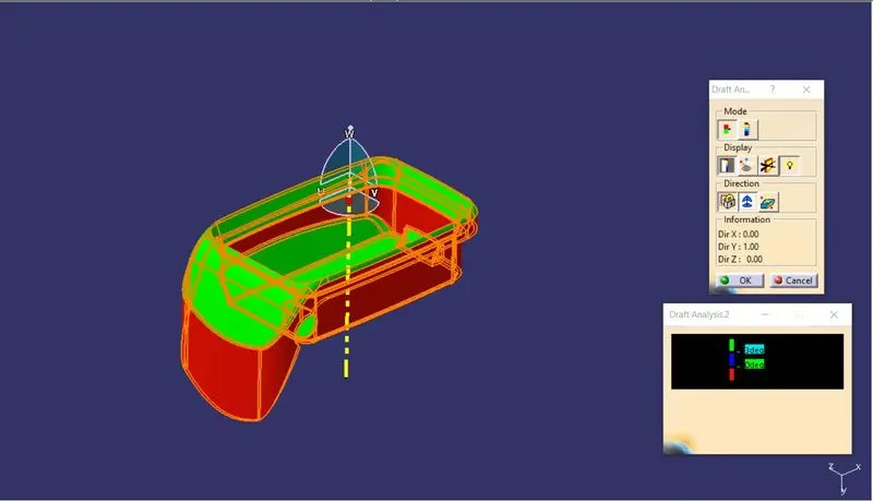
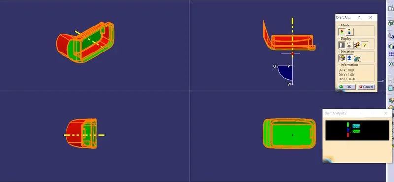
- Below image shows detailed draft analysis.
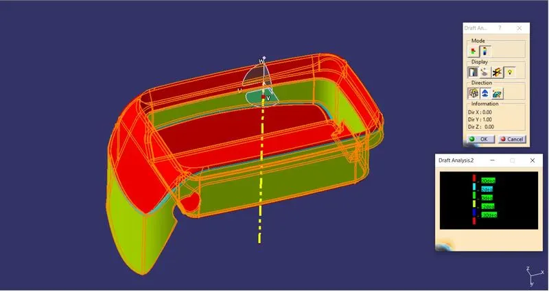
- Below image shows running point draft analysis.
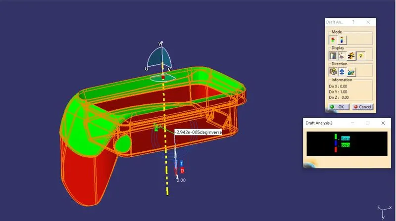
- Images of the solid model with the proper color code of the draft angle in various orientations (Isometric, Front, Side, and Top View).
ISO view:
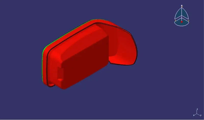
Front view:
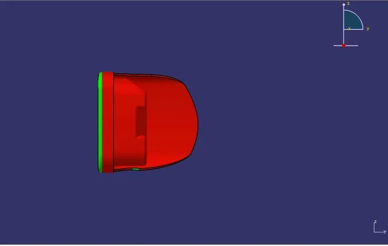
Left side view:
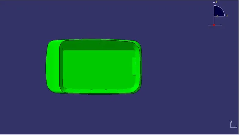
Right side view:
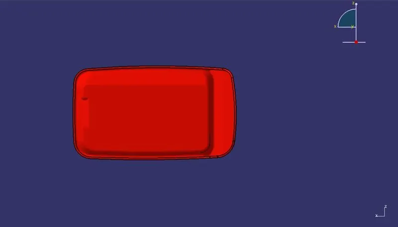
Top view:
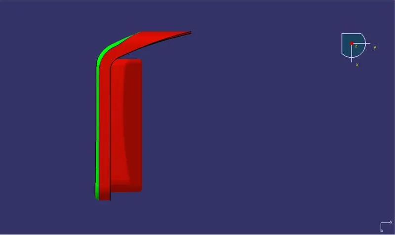
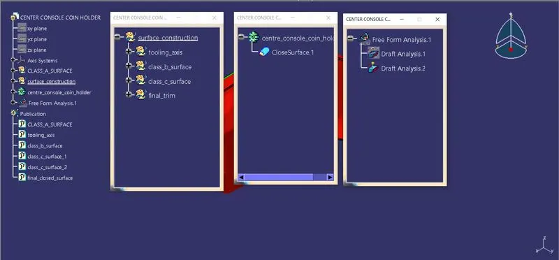
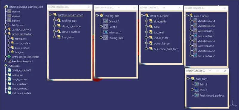
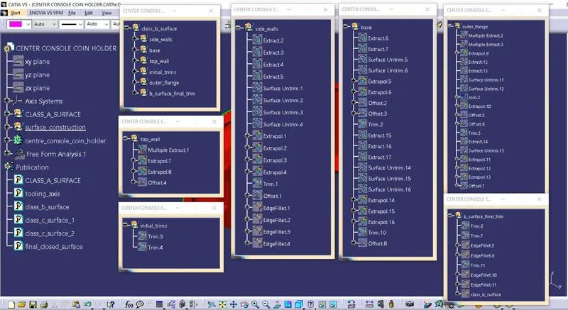
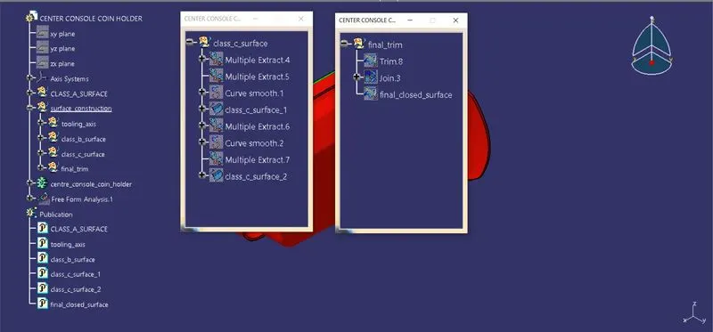
- Image of the expanded tree structure for the geometrical sets & part body.
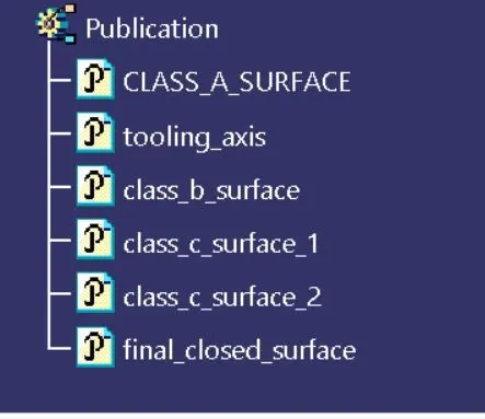
- Image of the publications of tooling axis & class A, B & C surface.