Week 8 - Challenge 4 - Coin Holder Design
Aim: To create Coin holder Design by creating Class A, B, C surfaces.
Objective: To create a Design and perform a draft analysis on it.
Introduction:
1. Class A surface: A surface given to the plastic modeller is of aesthetic and outermost surface. The surface made by the designer
is known as a Class A surface.
2. Class B surface: A surface that is below the Class A surface, at a certain thickness, which contains engineering aspects on it is
known as Class B surface.
3. Class C surface: A surface that joins the Class A and Class B surface is known as a Class C surface.
Procedure:
1. Creating a tooling axis
2. Performing draft analysis on Class A surface.
3. Creating a Class B surface
4. Creating a Class C surface
5. Creating a solid model and performing draft analysis.
Difference between Class A and Class B surface:
Class A Class B
Visible surface Invisible surface
The surface provided by the customer (OEM). The surface needs to be created w.r.t Class A surface.
Curvature continuity is present in surfaces. Tangent continuity is present in surfaces.
Ribs, bosses etc features are not present. Ribs, bosses, etc are present.
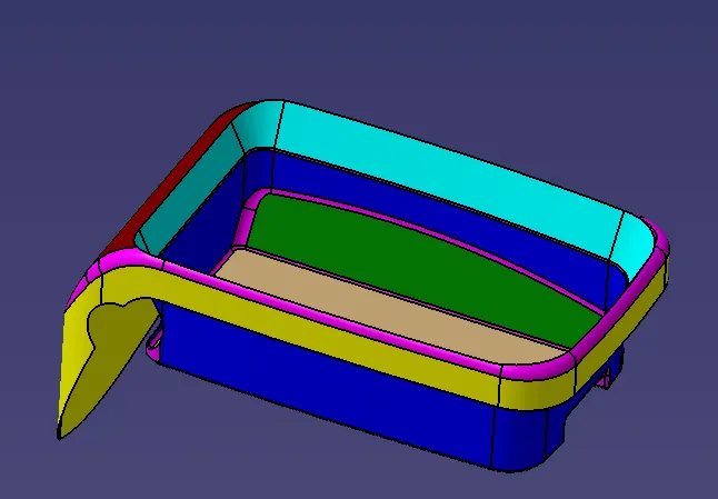
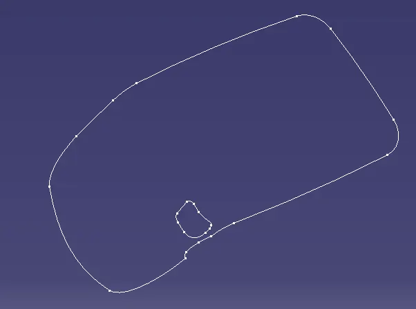
Creation of tooling axis:
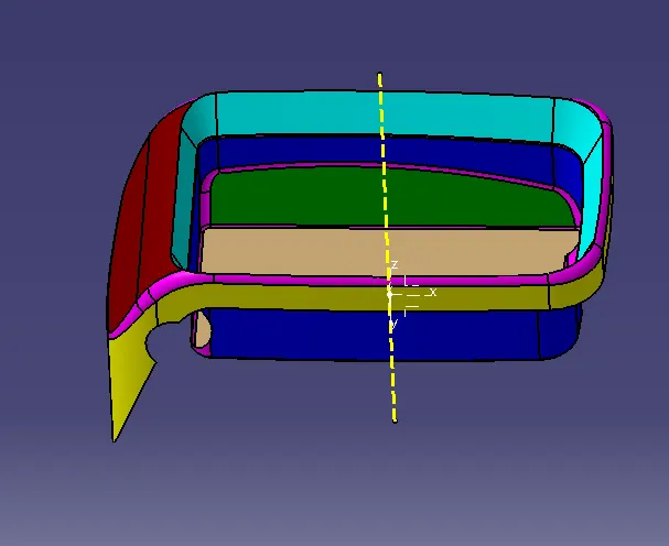
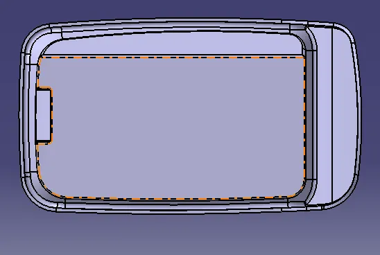
Since the model is a coin holder, which is like a bin, we can always take the tooling axis direction w.r.t the bottom surface as shown in the figure.
First, we need to check in all directions for the tooling axis for the core and cavity direction.
The draft angle needs to check for all surfaces so that no interference occurs while ejecting the core and cavity.
First, extract the bottom surface and create a point. With help of a point creates a line in the perpendicular direction of the surface.
Draft analysis:
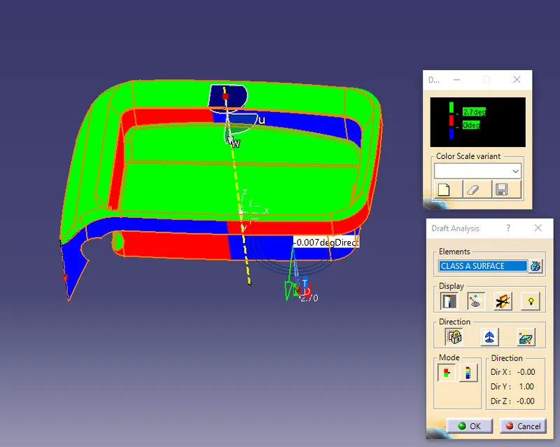
Now, perform draft analysis on the component by placing the compass in the tooling direction.
We can observe there are areas that show red in colour. This represents interference may occur while ejecting the component from
the core and cavity.
This occurred because of the surfaces of class A. The adjacent surfaces of the bottom surface are perpendicular to each other. We
know that we need surfaces with some draft angle so that component is easily manufactured.
The solution for this is changes need to be made on the class A surface with some draft angle.
Creation of Class B surface:
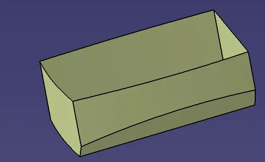
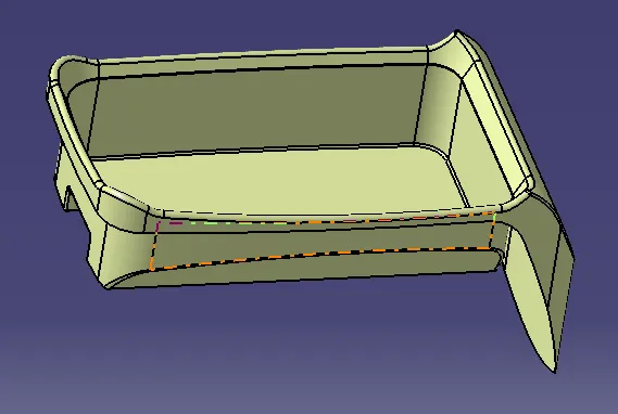
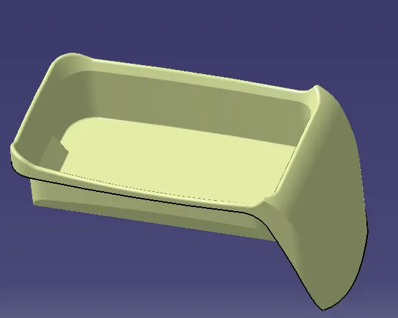
The below images represent the creation of the Class B surface.
First extracting the walls and Untrim the surfaces. The surfaces need to extrapolate and trimmed together.
The trimmed surface need to be offset with a 2.5 mm length. This is done because the thickness of the component is 2.5 mm.
This procedure is followed for all remaining surfaces and joined together to get a Class B surface.
CREATION OF CLASS C:
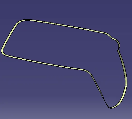
We can observe that the tooling axis is perpendicular to the joining of Class A and B surface. This cannot be drafted w.r.t tooling axis.
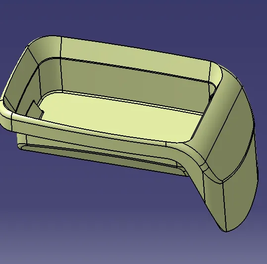
To join the Class A and B surface, the surface can be swept w.r.t the surface for an angle of 90 degrees.
After this joined together by trimming the surfaces and converting them into a solid
SOLID BODY:
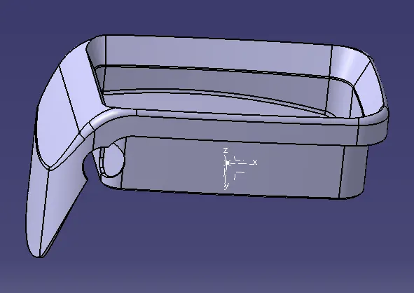
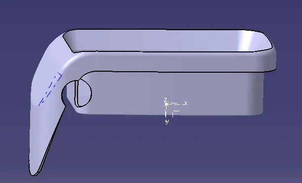
ISO-METRIC VIEWS:
top view:
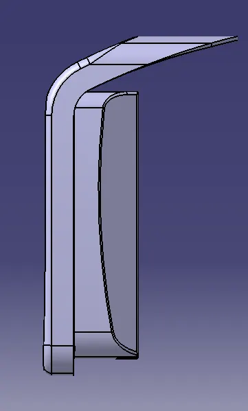
front view:
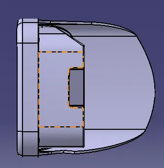
side view:
DRAFT ANALYSIS FOR A CLASS A SURFACE:
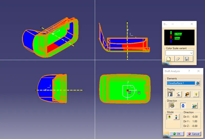
DRAFT ANALYSIS FOR A SOLID BODY:
We can observe that there are some areas that occur interference so draft analysis is not possible .
TREE STRUCTURE:
CONCLUSION:
Creation of Class B and C surfaces are done w.r.t given Class A. Draft analysis on a component failure due to the interference occurred at some areas.