Week 8 - Challenge 4 - Coin Holder Design
CENTER CONSOL COIN HOLDER
INTRODUCTION
In automotive design, a class A surface is any of a set of freeform surfaces of high efficiency and quality. Although strictly, it is nothing more than saying the surfaces have curvature and tangency alignment – to ideal aesthetical reflection quality, many people interpret class A surfaces to have G2 (or even G3) curvature continuity to one another (see free form surface modelling).
Class A surfacing is done using computer-aided industrial design applications. Class A surface modellers are also called "digital sculptors" in the industry. Industrial designers develop their design styling through the A-Surface, the physical surface the end-user can feel, touch, see etc.
A common method of working is to start with a prototype model and produce smooth mathematical Class A surfaces to describe the product's outer body. From this the production of tools and inspection of finished parts can be carried out. Class A surfacing complements the prototype modelling stage by reducing time and increasing control over design iterations.
Class A surfaces can be defined as any surface, that has styling intent, that is either seen, touched or both and mathematically meets the definition for Bézier.
- Automotive design application
- Product design application
- Aerospace design application
- Clay modelling
- Notable software
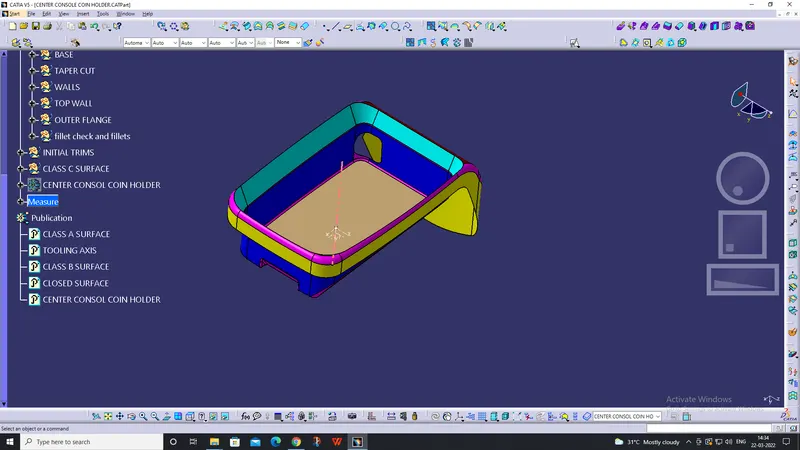
Class-A Surface: The top-most surface which is the present exterior of the component is said to be a Class-A Surface
Class-B Surface: The Surface which is interior to the component is said to be a Class-B Surface.
Class-C Surface: The Surface which joins the Class-A & 8 Surfaces is our Class-C Surface
Creating the tooling axis:
The tooling direction is used to find the direction in which the part is ejected out of the mold or it is the direction in
which the core and cavity are moved and the part is ejected. The draft on the part should be positive in order to manufacture the part easily. The draft angle should be positive with respect to the tooling direction.
To create the tooling axis, we need the proper orientation or view that gives the correct features and draft available in the component
So here the component view from the Y-direction gives the proper view for the tool to see the features present in the geometry.
make surface extract and give a center point,and as surface, are at 90 degrees make a axis normal to the surface
TOOLING AXIS
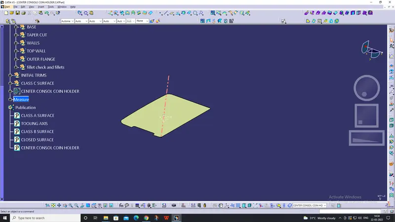
Class A surface withe color coding
Draft analysis:
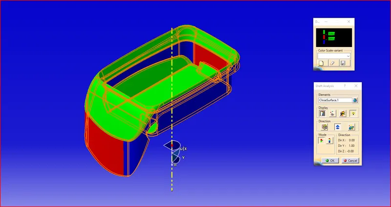
• To perform the draft analysis the view parameters are first set to material mode. Then go to insert analysis>>feature draft analysis.
• First, select the axis system and drag the axis system to align and coincide with the tooling axis and lock the
orientation. This axis system defines the draft direction according to the tooling axis
Switch on the color scale and set the minimum draft value. Here it is set to 3 degrees and it will be displayed in
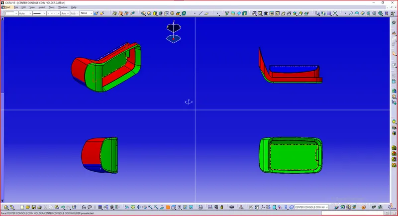
green color. Any draft angle below 0 degrees will be shown in red color. Now select the running point tool to measure the draft angle at the various locations and then if all surface passes the draft analysis switch on the light effect that will show the component in green color if the component has the required draft angle.
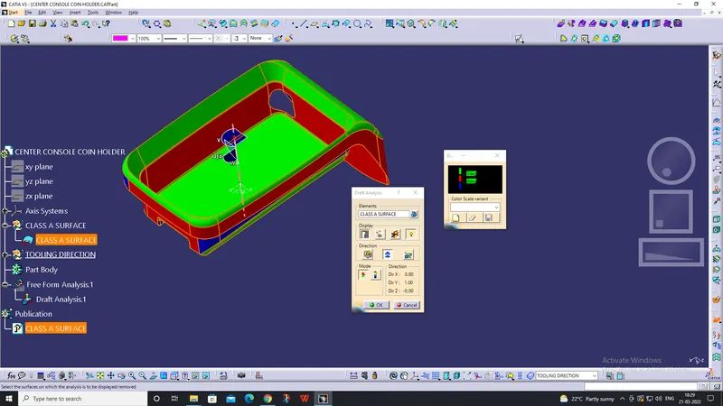
Class A draft analysis shows it has no draft angle in inner walls as they are placed in 90 degrees hence very hard to manufacture, and have to report it back to class A designer
PROCEDURE
*Class B surface WALLS after extract, Surface Untrim, Extrapolate, Trim.
*Class B surfaceCoin Holder after Extract, Offset, Surface Untrim, Extrapolate, Trim.
*Class B surfaceCoin Holder BASE after Extract, Offset, Surface Untrim, Extrapolate, Trim.
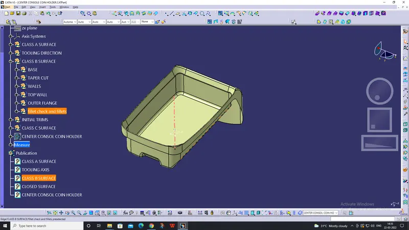
*Final Class B surface.
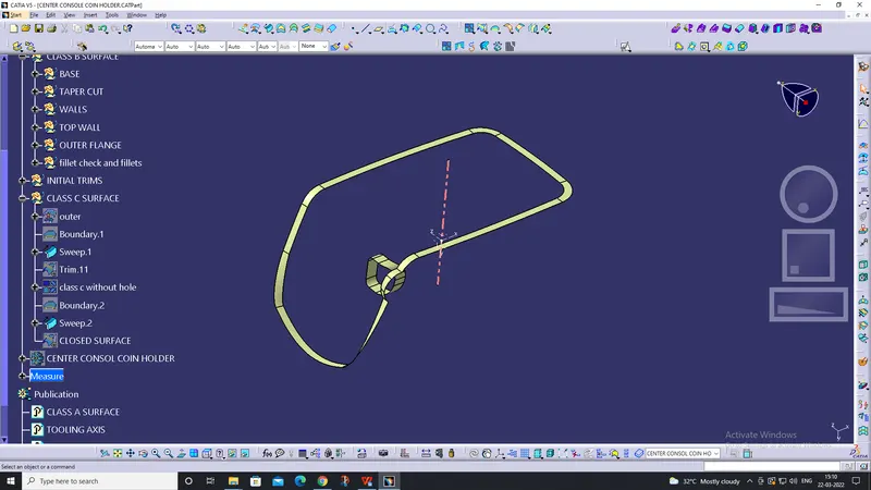
*Final Class C surface.
*Draft analysis for theCoin Holder by quick analysis mode.
*Draft analysis for theCoin Holder by Full analysis mode.
*Final surface of theCoin Holder with 2.5mm thickness.
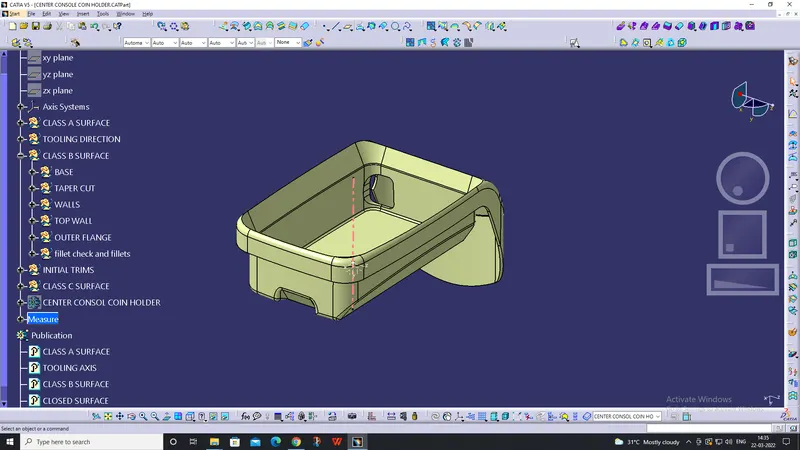
*Final surface of theCoin Holder with Close Surface.
class B surface created using extract from class a and offseting to thickness 2.5
Class C surface made using making boundry from class A ans making sweep to blass b surface
closed surface made by trimming class A B C surfaces
for solid part used close surface command
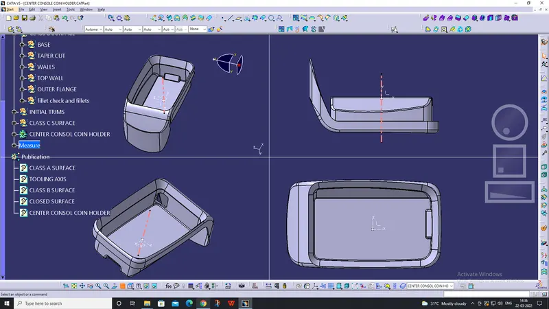
Final draft analysis
CONCLUSION:-
- A detailed report is been done explaining the draft analysis and the tooling axis creation.
- An explanation is been given on the way of creating the tooling axis by Bisecting method.
- Screenshots of the Draft analysis report.
- Image of the complete Draft analysis.
- Images of the color scale variant.
- Screenshots of the model with the proper color code of the draft angle in various orientations (Isometric, Front, Side, and Top View.
Problems in Class A designs
Class A design is not manufacturable as it has no draft value in inner walls, hence design is to be made again with some draft angle
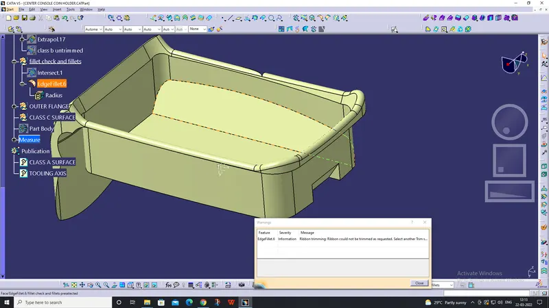
fillet values are to be clearly specified, from current fillet values cad model can not be made
at some places there are sharp edge that will lead to manufacturing issues , minimum fillets have to be used
non generated fillet