Week 8 - Challenge 4 - Coin Holder Design
COIN HOLDER CHALLENGE
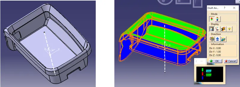
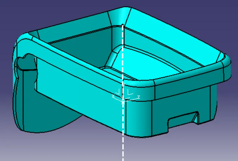
CLASS A SURFACE ANALYSIS :
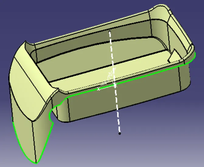
1) Initially we inspect the class A surface for any imperfections, open gaps, unjoined areas and any other issues which will affect the class B surface.
2) We see that there are no open areas and we can find two boundaries for the given class A surface.
- TOOLING CREATION FOR CLASS A SURFACE :
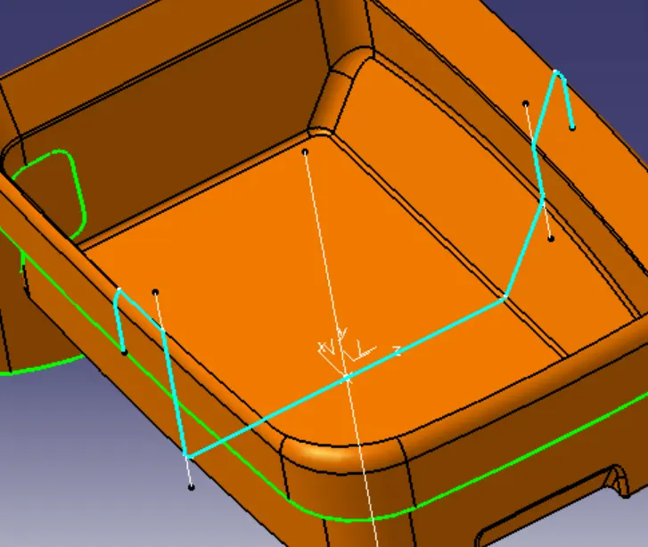
1) As there is a bucket shape in the middle of the part, we first consider the tooling in such a way to clear all the 4 faces of the dipped area.
2) Create a point in the center of the base surface and lets make tooling line pass through it always.
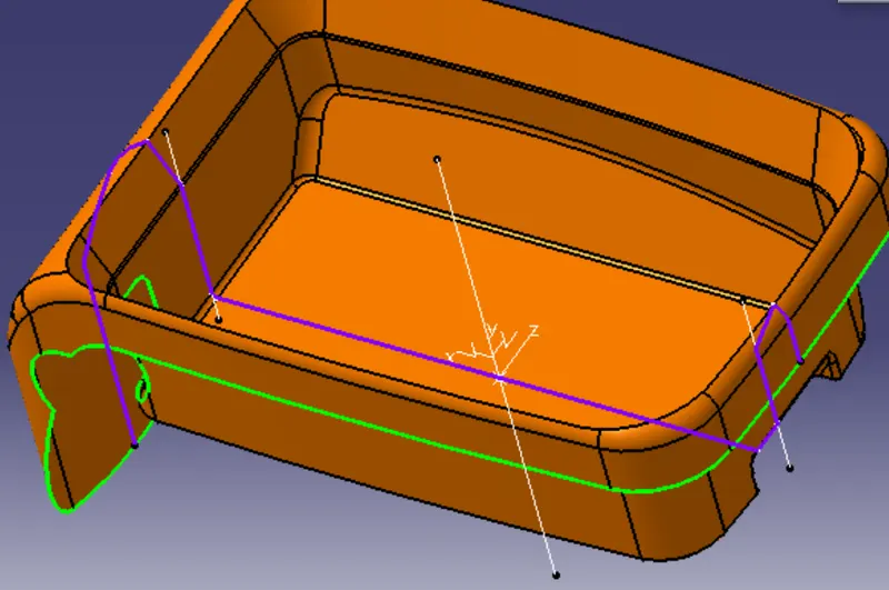
3) Take intersections along xy & xz planes along the given skin. We will use bisecting method to clear the surfaces.
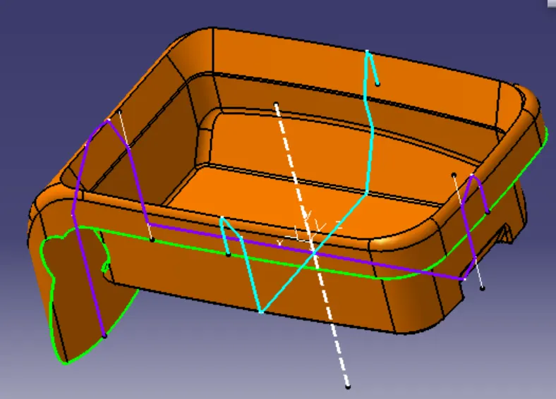
4) Now draw lines based on the intersection profile,totally we get 4 lines facing each other.
5) Create a bisecting line based on the XY intersection with the skin and also another bisecting line based on the XZ intersection with the skin.
6) Once we get these two lines, now create another bisecting line based on these two lines as input.
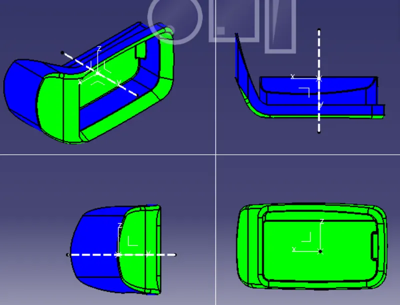
- DRAFT ANALYSIS FOR CLASS A :
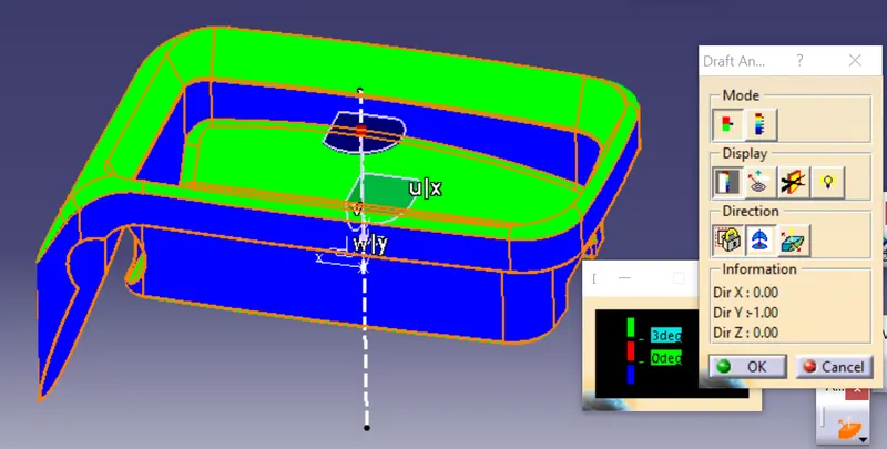
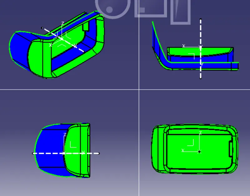
1) Once we place the compass on the MTD we have created we can see how the tooling will clear the class A surface.
2) The green surfaces have more than 3 degrees of draft which is sufficient to clear with the tool.
3) While the blue surfaces have 0 degree of draft with respect to our tooling direction. This means that these surfaces have not been given any draft while making the class A skin.
4)Even though we have used the proper method to create the tooling axis , our axis cannot clear this surface easily. Since they don't have draft we need to request the class A surface to be modified with proper draft angle for easy ejection from mold.
CLASS B AND CLASS C SURFACE CREATION :
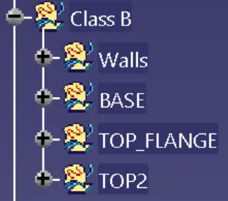
1) Once we fix the tooling axis we will work on the class B surface.
2) Since this part has many varying curvatures and complex shapes,it is important to work on individual features first and then trim eveything to form the final B surface.
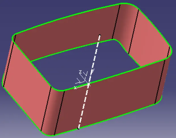
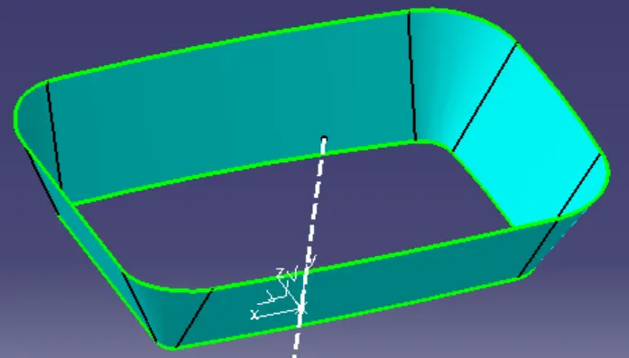
3) First we work on the walls, untrim the class A surface, extrapolate them and then trim with other faces. And finally offset the surface for 2.5mm
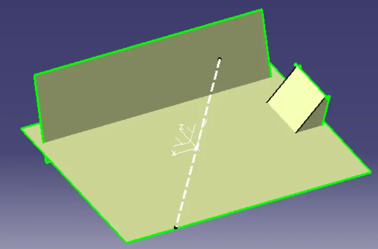
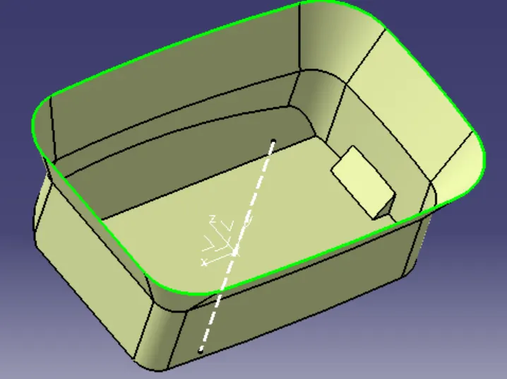
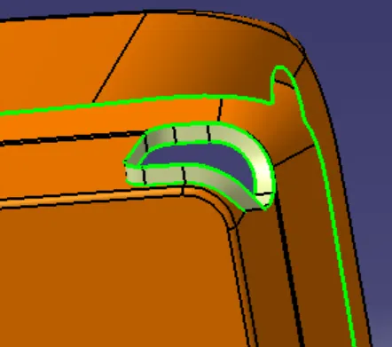
4) Then similarly we work on the base surface, upper flanges and the opening hole feature as well. Ignore the filleted areas and only work on the faces. Finally we can apply the fillet once we have the entire surface trim.
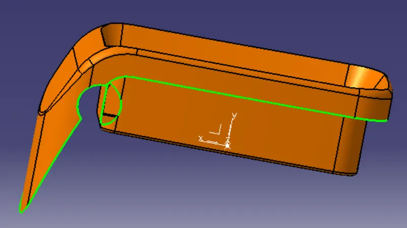
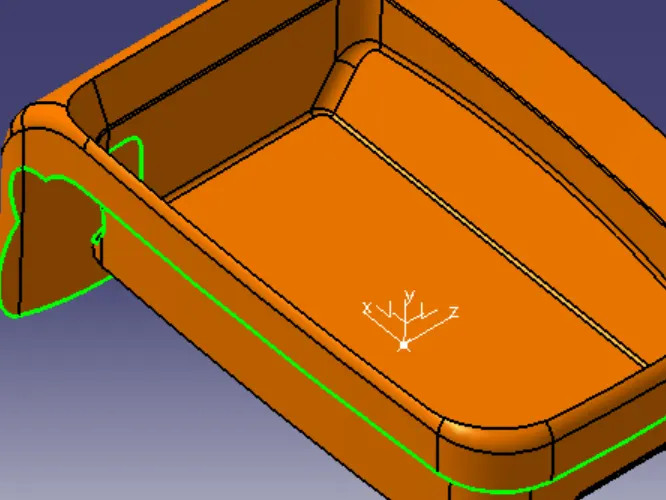
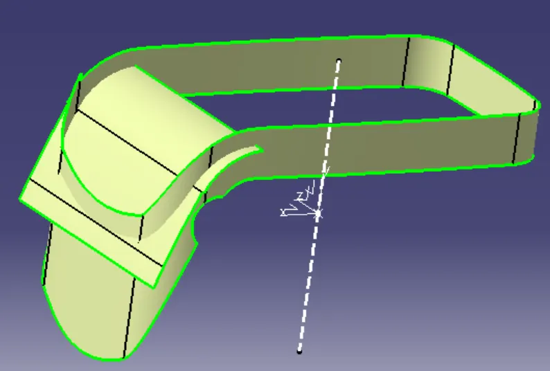
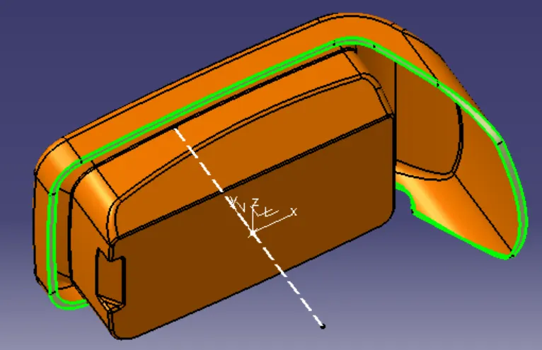
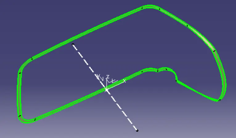
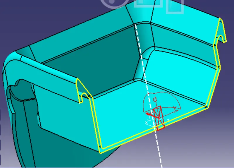
5) To form the CLASS C surface, select the entire boundary from class A skin and use SWEEP option with reference surface command to apply a 90 degree angle with the selected surface.
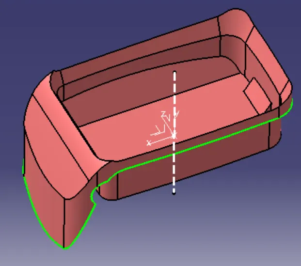
6) Trim the class C surface with class B deleting the excess portion. Now finally join the CLASS A , CLASS B & CLASS C surfaces.
DRAFT ANALYSIS FOR FINAL MODEL :
1) Now we place the compass on the created tooling direction and check the final model for tool feasibility.
2) As we understood by analysing CLASS A surface that some of the surface have been created with 0 draft angle, the same issue affects the CLASS B surfaces as well.
3) Wherever the draft angle is 0 (blue color) the same surface on the CLASS B have 0 degree drat with respect to our tooling axis.
4) We must ensure that CLASS A surface is properly created with sufficient draft before we move on to the class B and class C surfaces.