Week 8 - Challenge 4 - Coin Holder Design
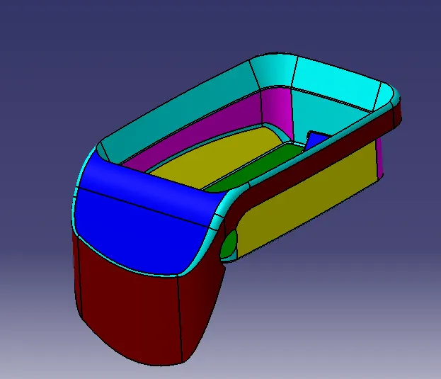
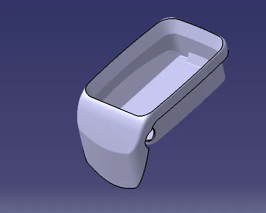
OBJECTIVE - Create the Coin Holder Plastic component through the given Class-A surface.
PROCEDURE-
- check is there any open boundaries present or not which may create errors while designing by using boundary option.
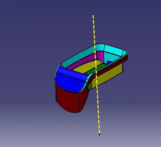
- The tooling axis is the direction of drawing a sheet metal where the finished component is easily ejected on a particular direction and axis. The tooling axis is important for removing the material when finished.
- First, we have to create An Axis system, from that axis system we will get two cross-sections. by using that cross-section lines we will create the tooling axis for the surface.
- for this component we have crated a tooling axis with respect to the point and y component so that it will give a standard view while drafting.
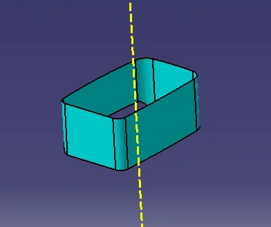
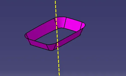
- Now extrude the side walls in the new geometrical set we named it as side walls and untrim the walls and extrapolate it to get closed surface with intersection.
- Apply the fillets with respect to the class A surface.
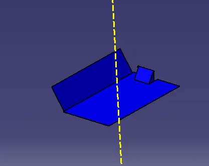
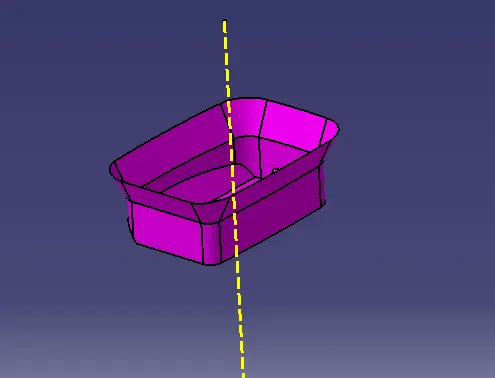
- Now unhide the class a surface and extrude the horizontal and inclined base in the new geometrical set name it as BASE then untrim it and then extrapolate both the surface so that we will have a interaction between the surfaces
- Offset both the surfaces at 2.5mm distance and then trim the unwanted surfaces.
- Repeat the same procedure for the end part.
- Now extract the top wall from the class A surface in the new geometrical surface and extrapolate it name it as top wall and then offset it at the distance of 2.5mm
- Now insert a new gemotrical set and name it as Initial trim and trim the base wall with the side wall
- now trim the top wall with the last trim surface to get a complete closed box
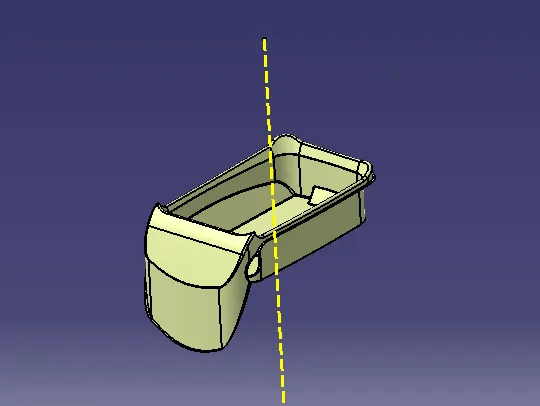
- After completing the box, extrude the outer flange from the Class A surface
- untrim the surfaces and then extrapolate it.
- if the extrapolate doesn't connects then extract the boundaries of each surface so that you will get the intersection the trim the surfaces and then offset it at a distance of 2.5mm
- create the boundary for outer flange and sweep it and then trim it with the flang to get the closed flange
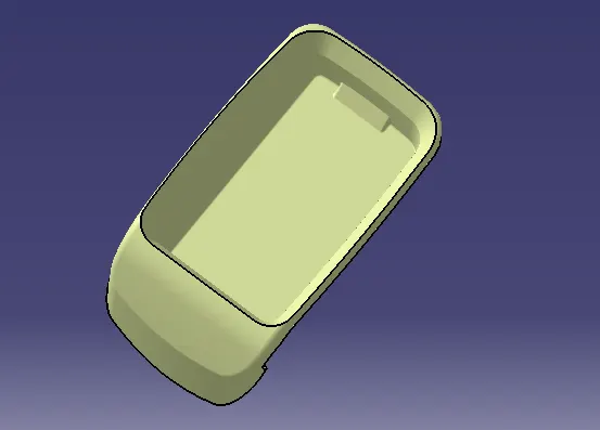
- and repeat the same for the hole and trim the class c surface with the class B then join the class A and class b surface and trim it with the class b surface
- now jump into part workbench and using closed surface option make a solid body then perform drafting
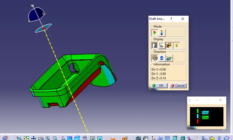
- first enable the tooling axis and drag the compass on the tooling axis and now lock the compass and click any where on the draft if the class A and class C surface shows green color it means model is passed in the drafting.
- Green color indicates that the model passed in the draft analysis also it represent the draft angle of 2.9 and above 2.9
- Blue color indicates that the model darft angle is 0 deg.
- Red color defines the negative draft angle or less than zero draft angle.