Week 8 - Challenge 4 - Coin Holder Design
Coin holder
AIM: to perform draft analysis and make a solid model from the given class a input.
Tools used:
Boundary, join, multiple extract, bisecting line, draft analysis, intersect, sweep, close body surface, extrapolate.
Procedure
- Creating tooling axis
- Open the given CAT part file.
- check for gaps between surfaces for that click on join and then preview
- find the correct tooling axis where the material don’t interfere with the tooling axis and all the elements can be created
- create an axis system using the surface at the bottom and use point to create the axis system
- Intersect the yz plane with respect to the class a surface walls.
- Create a line in zx plane at 6 degree with respected to intersection
- Hide the class A surface and create point to point lines on the suspected drafts
- Create a bisecting line with the two lines and point to create a tooling axis
- The tooling axis is created for the component
Coin holder
AIM: to perform draft analysis and make a solid model from the given class a input.
Tools used:
Boundary, join, multiple extract, bisecting line, draft analysis, intersect, sweep, close body surface, extrapolate.
Procedure
- Creating tooling axis
- Open the given CAT part file.
- check for gaps between surfaces for that click on join and then preview
- find the correct tooling axis where the material don’t interfere with the tooling axis and all the elements can be created
- create an axis system using the surface at the bottom and use point to create the axis system
- Intersect the yz plane with respect to the class a surface walls.
- Create a line in zx plane at 6 degree with respected to intersection
- Hide the class A surface and create point to point lines on the suspected drafts
- Create a bisecting line with the two lines and point to create a tooling axis
- The tooling axis is created for the component
Creation Of Tooling Axis-
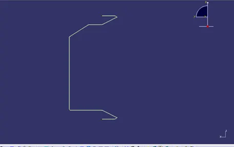
To create a tooling axis, extract the bottom face and take a point on that bottom surface to create Axis system. After taking Axis system, intersect Class A part with YZ plane of Axis system
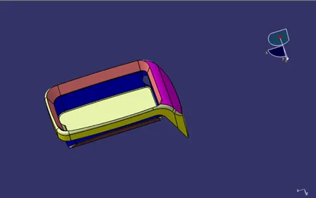
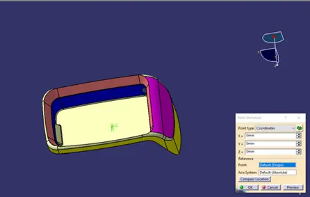
Here nothing any complex geometry so we can create tooling axis perpendicular to extracted base surface because the walls are at 90 degrees.
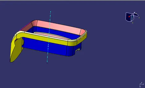
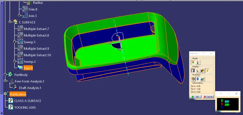
- Draft analysis
- Before going to drat analysis go to customized view parameter >under mesh >check material and then click ok
- Now for draft analyses go to insert >analysis>feature draft analysis.
- Use the compass to define the draft direction
- In the colour scale change the draft angle to 3degree.
- The component changes to green in indication of passing draft angle.
- Use running point to check the angle on the component.
- The draft analysis is complete.
- Creation of class B surface
- Extract the surfaces from the class a using multiple extract and untrim them
- Use extrapolate to make sure that all the untrims are properly intersected to trim and offset the surfaces to 2.5 mm to create the thickness.
- Trim the extra surfaces using trim command
- Insert them into new geometrical set and name it with respective part names.
- Apply fillets to the model after creating the entire surface.
- Perform trims one at a time so that it will be clear to understand.
- Creation of class c surface
- Extract the boundary from the class a surface using boundary.
- Use sweep command >choose profile type line>subtype as with reference to surface >choose guide curve and choose reference surface >give angle as 90degree>give distance>preview.
- Use smooth curve to reduce the patches and get clean surface.
- Trim class A and class B surface.
- Check for boundary if any there ,then extrapolate the class A to 0.05mm ad then trim it with class C
- After getting sweep then join the class c and trim to get final output.
- Now open part design workbench and using close body surface create a solid of the component.
- After getting close body surface conduct draft analysis some parts of the component have a draft of 2.9 degree modify the draft and for the main wall the tooling axis must be modified.
To create Class B surface, extract and untrim the sidewalls from Class A part and trim as per requirement after offsetting them by 2.5mm because the thickness is given.
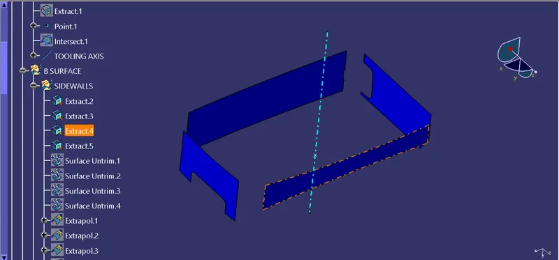
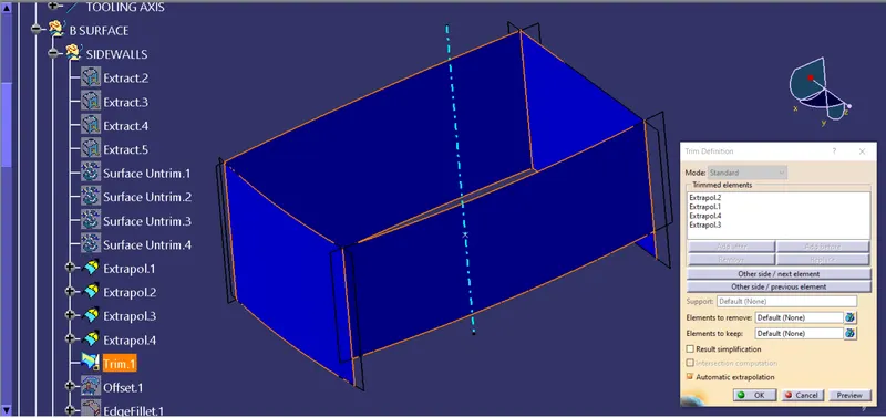
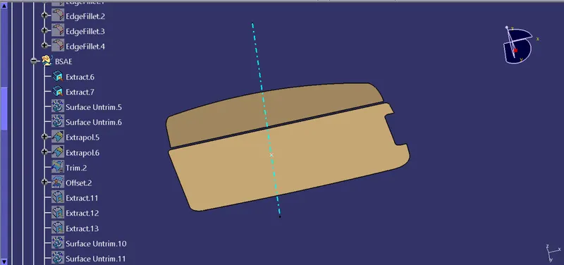

To create top walls, use multiple extracts and extrapolate them as per requirement.
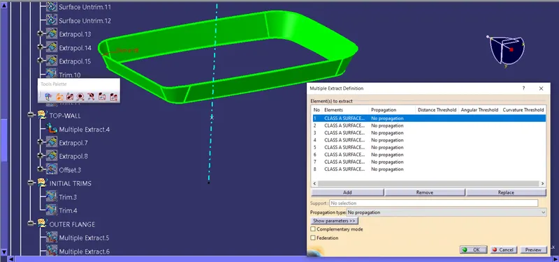
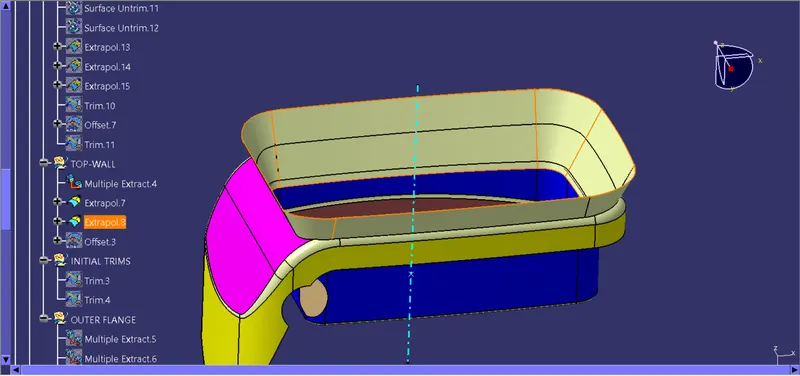
Apply fillets to the walls. During giving outside fillets add the thickness value and viveversa.
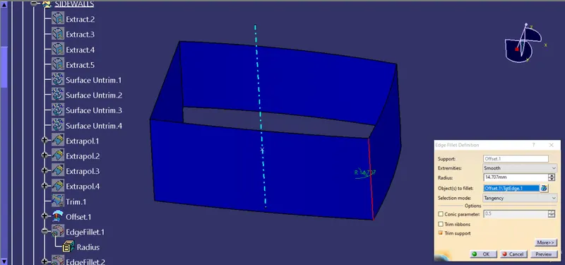
Now trim the surface as per requirement.
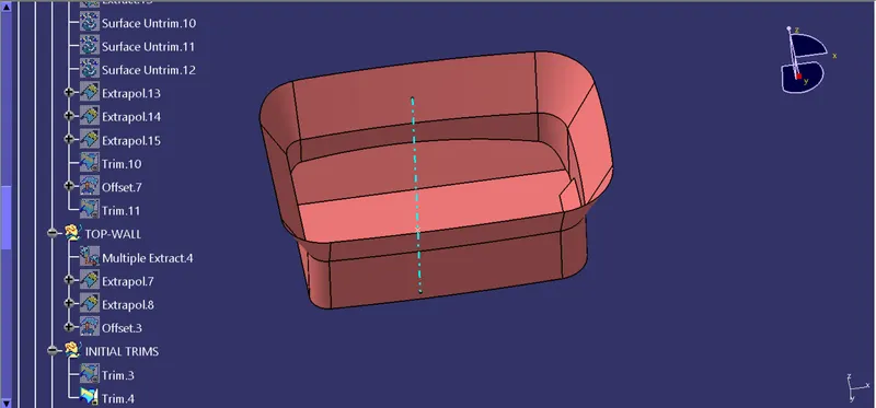
Now for extrnal remaing part, use multiple extrats and extrapolate them and then trim it and offset by 2.5 mm.
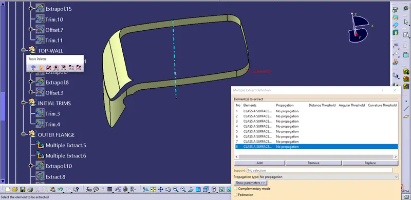
Now extract the remaining small surface and extrapolate them and trim it with a class B surface.
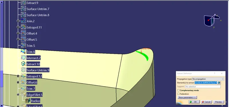
Creation Of Class C Surface-
To creeate Class C surface, use multiple extracts on outside walls & use Boundry for that surface for using sweep command.
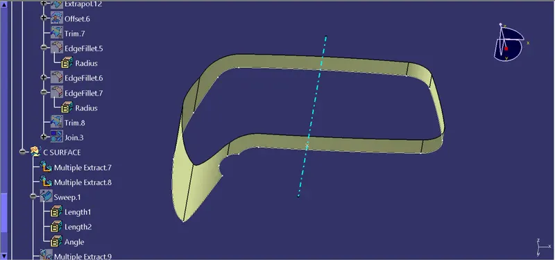
Use, with the reference surface type in a sweep operation give 4 mm length for a sweep and select extracted surface for the referance. And angle should be 90 degrees.
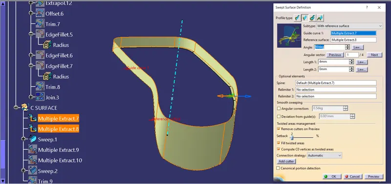
Perform same procedure with for inner boundry, and join it with the class A surface.
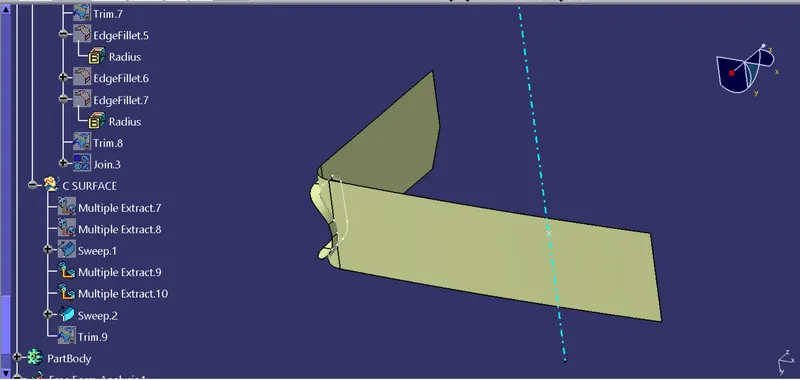
Now trim between Joined surface & class B surface.
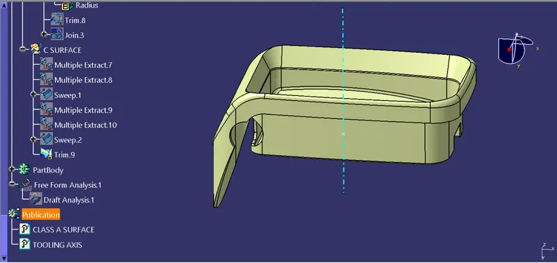
DRAFT ANALYSIS-
Do draft analysis on the surface along the tooling axis.
Isometric View-
Front View-
Right View-
Left View-
Top View-
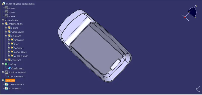
conclusion:
thus Creation of the Coin Holder Plastic component through the given Class-A surface with that we created class b & c to make it close surface and also draft analysis has been done